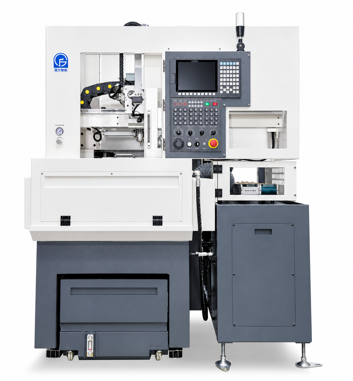
L3 CNC Lathe with Automatic Loading and Unloading Robot
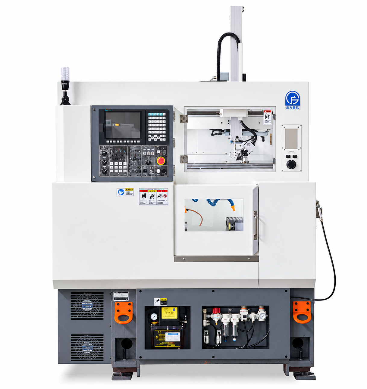
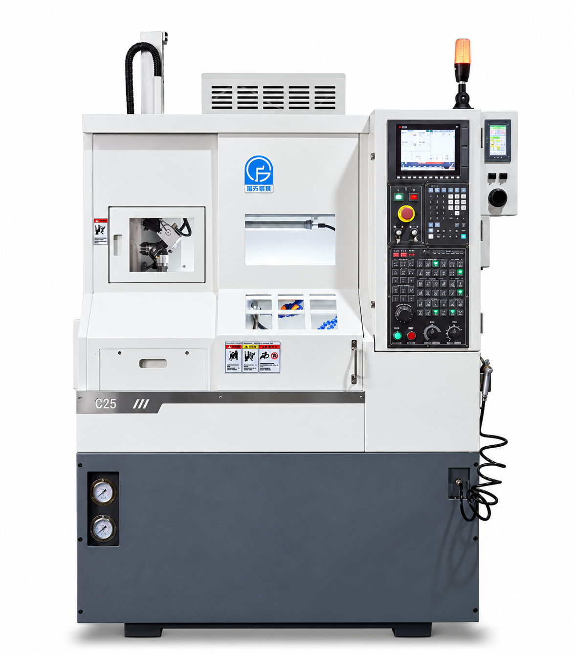
The L3 is a compact CNC lathe configured for automated workpiece handling. It features a 5.5 kW spindle motor, a maximum spindle speed of 6,000 rpm, and a loading robot and conveyor listed among its standard accessories.
- MOQ: 1 set
- Brand: SIPENG CNC — Tianjin, China
- Configuration: Tooling / bar feeder / parts collection / automation
- Quotation: reply within 24 hours
Specifications
| Machine model | L3 |
|---|---|
| Maximum bar capacity | 35 mm |
| Maximum turning diameter | 200 / 85 mm (as listed; confirm the meaning of each value) |
| Maximum turning length | 120 / 50 mm (as listed; confirm the meaning of each value) |
| CNC control | In-house 808; Mitsubishi E80 / M80 optional |
| Spindle nose | A2-4 |
| Spindle motor | 5.5 kW |
| Maximum spindle speed | 6,000 rpm |
| X-axis travel | 320 mm |
| Z-axis travel | 280 mm |
| X-axis ball screw | 2510 |
| Z-axis ball screw | 2510 |
| Bed construction | One-piece cast bed; high-rigidity moving-spindle structure |
| Machine guarding | Fully enclosed sheet-metal guarding |
| Footprint (W × D) | 1,477 × 1,850 mm |
| Machine height | 1,995 mm |
| Machine weight | 1,650 kg |
| Unloading takt | 8 s; confirm measurement conditions and definition |
Product Details
L3 CNC Lathe with Automatic Loading and Unloading Robot
Machine Overview
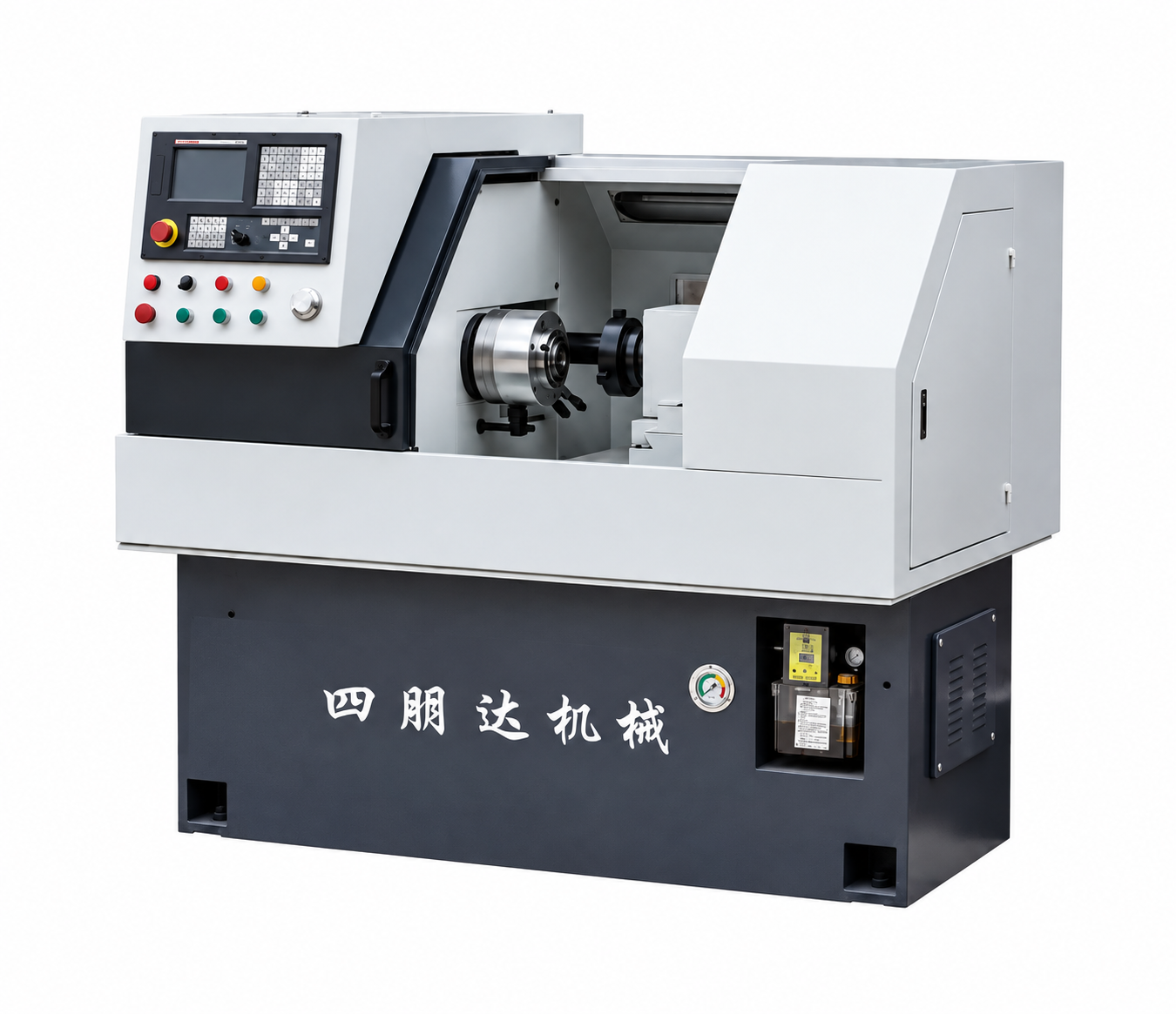
The L3 is a compact CNC turning platform configured for automated workpiece handling. Its documented configuration includes a loading robot and conveyor. The machine features a one-piece cast bed, a high-rigidity moving-spindle structure, and fully enclosed sheet-metal guarding.
Turning Capacity
- Maximum bar capacity: 35 mm
- Maximum turning diameter: 200 / 85 mm, as listed in the source document
- Maximum turning length: 120 / 50 mm, as listed in the source document
Capacity note: The source document does not define what each value in the diameter and length pairs represents. Confirm the applicable values for the selected machine configuration before publication or ordering.
Technical Specifications
| CNC control | In-house 808; Mitsubishi E80 / M80 optional |
|---|---|
| Spindle nose | A2-4 |
| Spindle motor | 5.5 kW |
| Maximum spindle speed | 6,000 rpm |
| X-axis travel | 320 mm |
| Z-axis travel | 280 mm |
| X-axis ball screw | 2510 |
| Z-axis ball screw | 2510 |
| Footprint (W × D) | 1,477 × 1,850 mm |
| Machine height | 1,995 mm |
| Machine weight | 1,650 kg |
Standard Accessories
- Hollow rotary cylinder × 1
- Tool-setting blocks × 2
- Double-row tool posts × 2
- Single-row tool posts × 3
- Large-capacity coolant tank with settling and filtration
- Coolant pump system with high-pressure pump
- Full sheet-metal enclosure
- Automatic lubrication system
- Loading robot and conveyor
Optional Equipment
- Automatic bar feeder
- Automatic chip conveyor
- Chuck or collet
- Dedicated workholding fixture
- In-process measurement
- Workpiece turnover unit
- Through-spindle coolant
Unloading takt: The source document states an 8-second unloading takt. This figure is the stated unloading takt; confirm its measurement conditions and definition with the manufacturer. It should not be presented as the complete machining cycle time.
Machine configuration and optional equipment should be confirmed for the intended application.
Send your requirement and quantity — we reply with price, lead time and technical advice within 24 hours.