How to Set the Infeed on a Hydraulic CNC Turning-Square Machine
A practical setup method for controlling material removal, across-flats size and repeatability on CF-50HPC and CF-60HPC hydraulic CNC turning-square machines.
How to Set the Infeed on a Hydraulic CNC Turning-Square Machine
A practical setup method for controlling material removal, across-flats size and repeatability
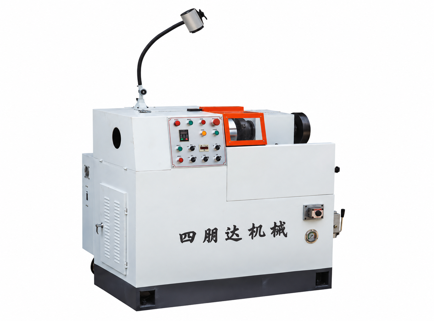
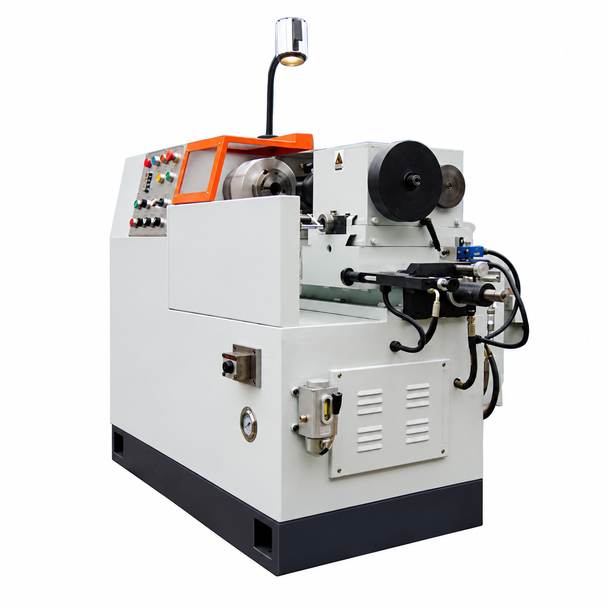
CF-50HPC / CF-60HPC hydraulic CNC turning-square machine
Start with the finished dimension
“Infeed size” can mean different things on a turning-square machine. The finished across-flats dimension is a part requirement; radial infeed is the tool penetration or stock removed during a cut; feed rate is how quickly the slide advances. These settings interact, but they are not interchangeable. Set the target from the drawing, then identify the machine control or mechanical adjustment that actually changes the cutting position.
Setting | What it controls | How to verify |
Across-flats size (AF) | Finished distance between opposing flats | Measure the part with a suitable micrometer or across-flats gauge. |
Radial infeed / cutting depth | Tool penetration or material removed per cut | Use the designated offset, stop or adjustment specified for the exact machine. |
Feed rate | Advance speed during the cutting cycle | Adjust for stable cutting and finish; feed speed alone does not define final AF size. |
The supplied CF-50HPC / CF-60HPC product sheet lists stepless feed adjustment and a hydraulic spring-collet clamping device. It does not identify a specific infeed dial, offset scale or adjustment direction. Confirm the control method on the exact machine before setting a value.
Understand the machine setup before changing an adjustment
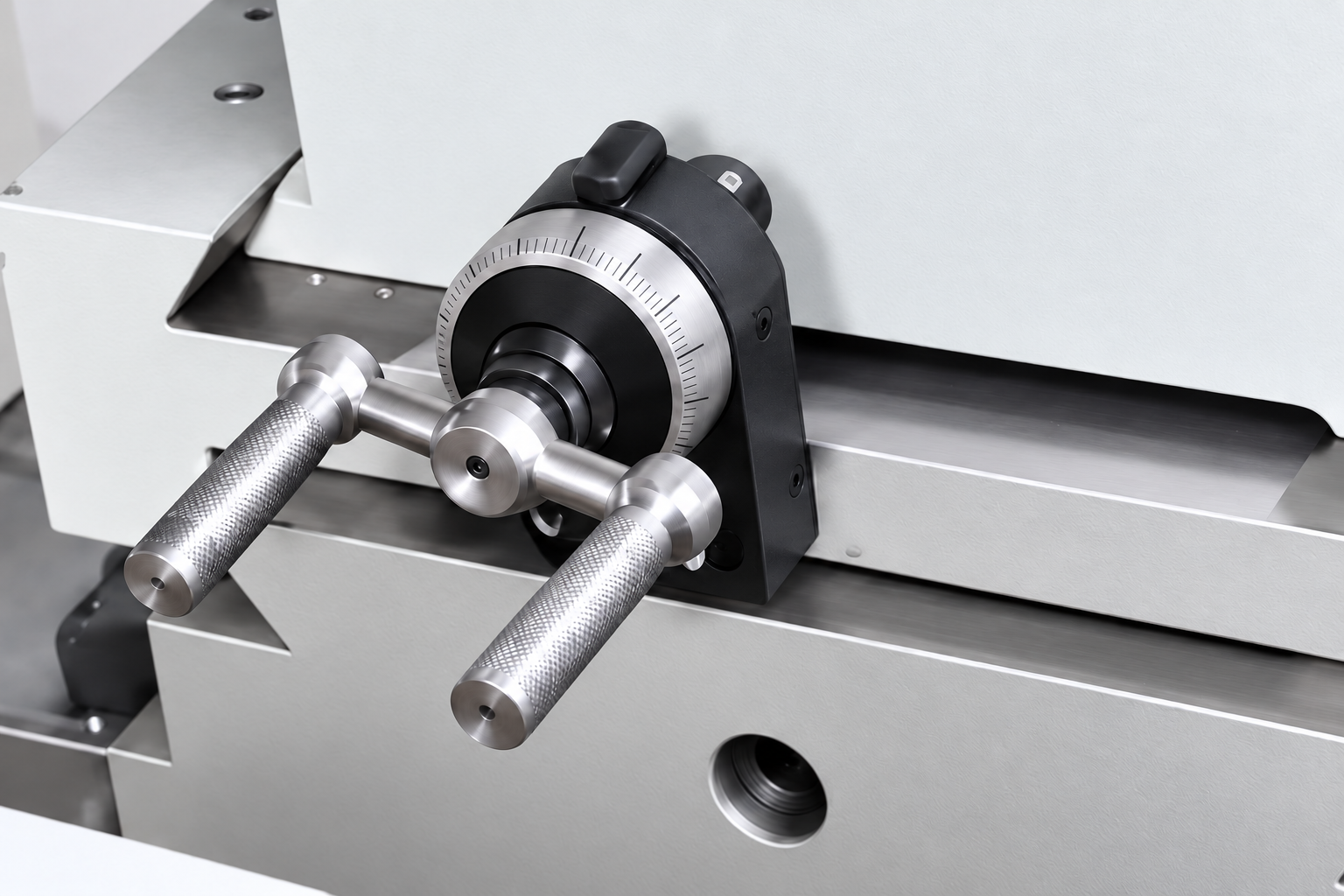
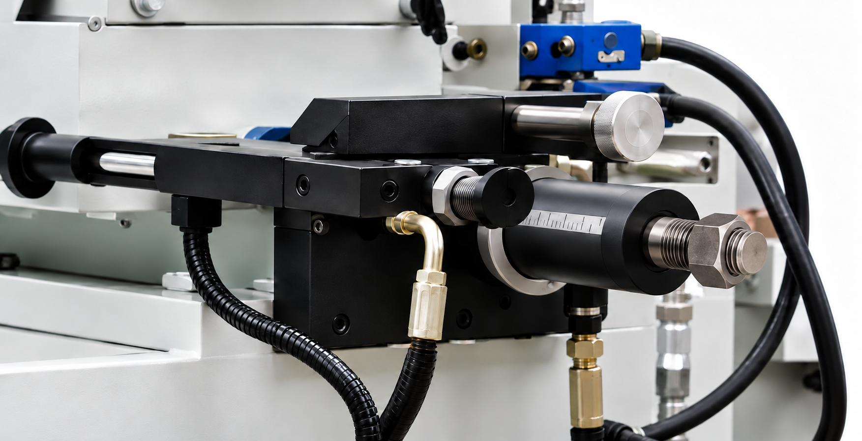
The selected cutter holder and its cutting edges establish the tool geometry. The workholding system locates and grips the blank. The machine’s designated infeed control or stop establishes the cutting position, while the feed setting governs the advance speed. A dimension change should be made through the correct cutting-position adjustment—not by increasing hydraulic clamping pressure.
A controlled setup sequence
1. Read the drawing. Record the target across-flats size, tolerance, flat count, part length, material and required surface condition. Confirm whether the dimension is measured before or after deburring.
2. Prepare the blank and holding system. Check stock size, straightness, burrs, collet range, seating and runout. Use the shortest practical stickout and the gripping length recommended for the part and cut.
3. Install the specified cutter holder and cutting edges. Confirm the holder type matches the required flat count, the edges are seated and indexed correctly, and the tool assembly is secure. Follow the machine maker’s setup procedure.
4. Establish the machine reference. With the spindle stopped and the machine in the prescribed safe setup state, set the designated reference, offset or mechanical stop. Do not assume that a handwheel, stop or hydraulic control has the same function across machine versions.
5. Make a conservative first test cut on a sample blank. Keep guards in place during operation. Measure the resulting across-flats dimension after the part is safely removed and cleaned.
6. Correct one variable at a time. Use the measured error to adjust the designated cutting-position setting, lock it, and make another test cut. The relationship between the adjustment movement and AF change depends on the cutter arrangement; establish it by measurement rather than assuming a 1:1 correction.
Measure, correct and confirm
Measure across opposing flats at more than one position along the part. If the part has multiple flat pairs, check each pair. Where the tolerance is tight, use an instrument suited to the drawing tolerance and confirm the measuring method before production.
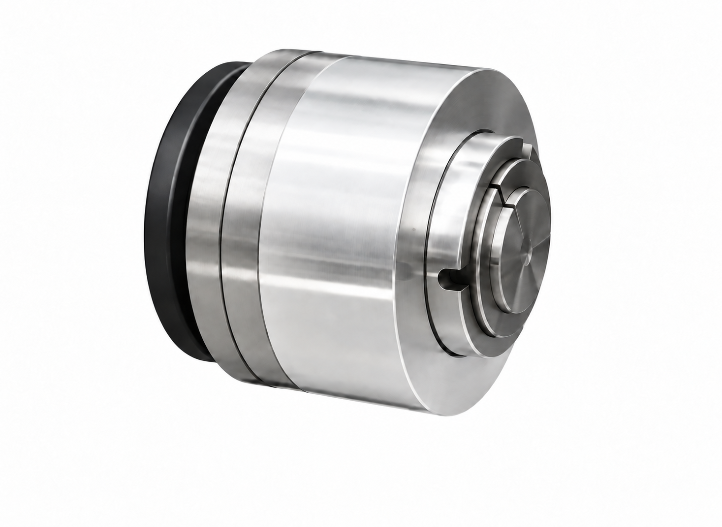
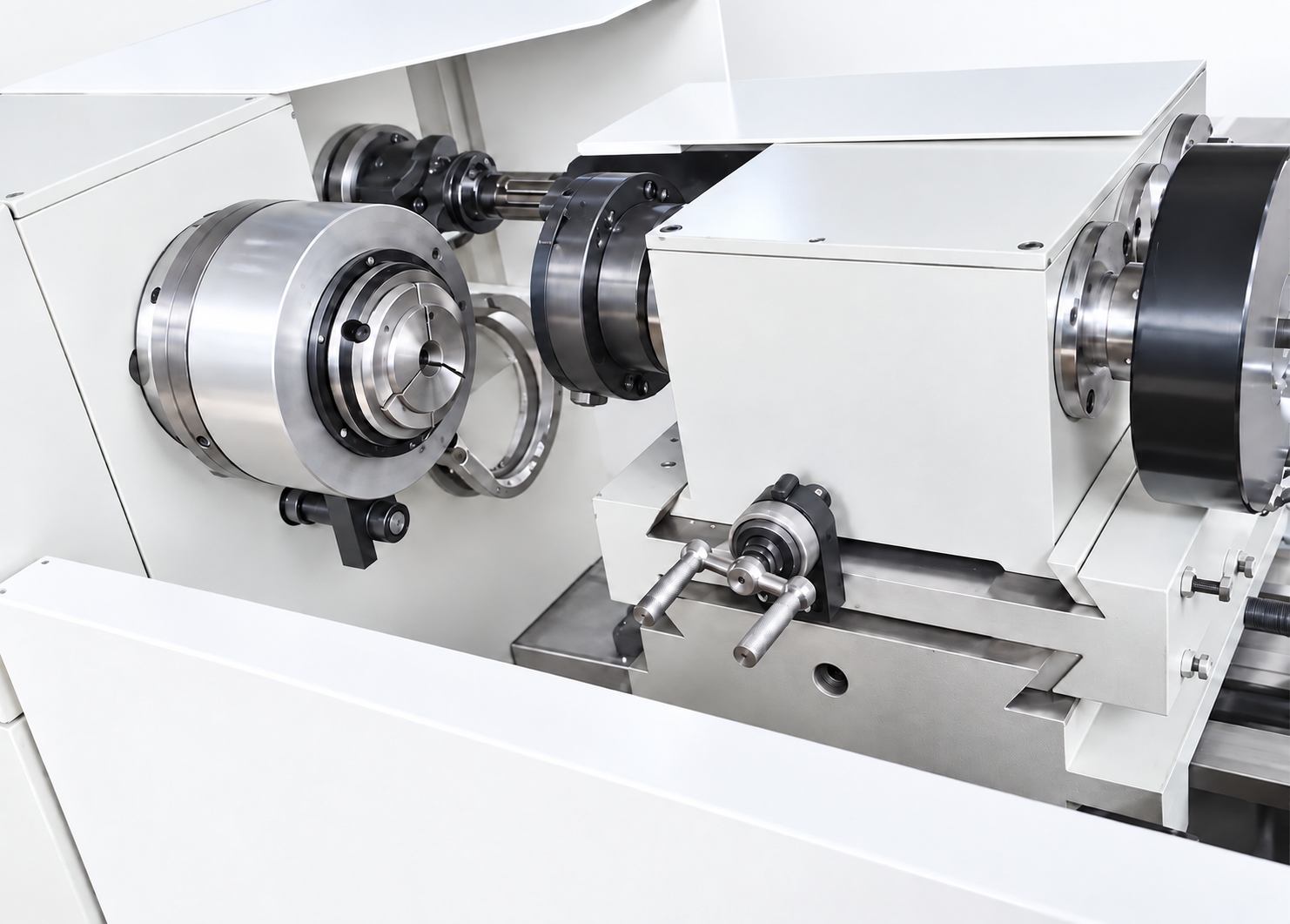
Hydraulic chuck shown in the supplied machine materials
Use the measurement to guide the next adjustment
· If the across-flats size is too large, verify the reference, tool projection, holder seating and blank runout first. Then move the designated cutting-position adjustment in the direction that increases material removal, as defined by the machine manual.
· If the across-flats size is too small, verify the same setup points and correct the designated cutting-position setting in the opposite direction. Do not compensate by changing clamping pressure.
· If opposing flats are unequal, inspect cutter-head alignment, edge indexing, tool wear, workpiece orientation and collet seating. A single overall offset may not correct a geometry or alignment error.
· If the dimension changes along the part length, check tool alignment, feed path, support, workpiece stickout and cutting-edge condition. Confirm whether the drawing allows taper or requires a parallel result.
· If chatter, burrs or poor finish appear, check clamping, overhang, tool sharpness and cutting conditions. Do not simply increase pressure; excessive clamping can deform the blank.
A practical first-piece approval check
After the final test cut, verify the across-flats size, flat-to-flat consistency, burr condition and surface finish. Check the part after unclamping because the workholding force can affect a thin or flexible blank. Record the approved tool setting, feed setting, blank size, clamping setup and measurement result so the next setup can be reproduced.
Before production
· Confirm the exact machine model and the function of each infeed and feed control.
· Confirm the cutter holder, cutting-edge geometry and flat count for the part.
· Check the blank, collet, clamping length, runout and safe tool clearance.
· Lock all adjustments after the test cut and follow the machine maker’s guarding and setup rules.
· Inspect the first part and repeat checks after tool changes, blank-lot changes or setup changes.
Important machine-specific note
The supplied CF-50HPC / CF-60HPC brochure shows the machine, cutter-head unit and standard/optional configurations, but it does not show a detailed adjustment diagram or a numeric infeed procedure. The steps above are a process-control method, not a substitute for the exact machine manual. Confirm adjustment direction, increment and permitted range with the machine supplier before applying a production setting.
Send us your drawing or sample — our engineers review material, tolerances and cycle time, and reply with a machine & process recommendation.
Discuss Your Part →