Vibration-Based Collision Monitoring for CNC Machine Tools
An engineering overview of vibration-based collision monitoring for CNC machine tools, covering machine-state baselines, alarm tuning, CNC/PLC integration, commissioning, and claims that should be verified before use.
Vibration-Based Collision Monitoring
for CNC Machine Tools
Operating principle, integration considerations, and validation
A collision or abnormal impact can damage a tool, workpiece, fixture, spindle, or machine structure and interrupt production. A vibration-monitoring system can add an early-warning layer by tracking machine vibration and flagging patterns that exceed configured limits. Its value depends on sensor placement, machine-state baselines, alarm tuning, and a verified response path.
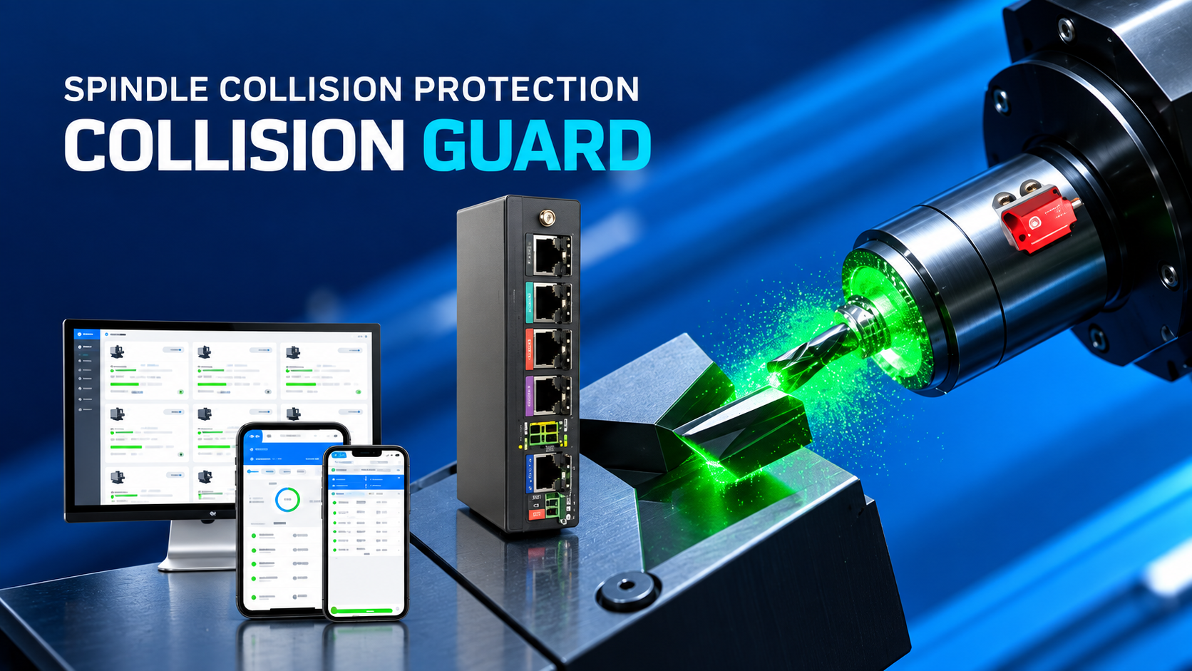
The supplied video shows a system branded “Collision Guard” by Weizhen Technology. It depicts a spindle-area vibration sensor, monitoring software, alarms, machine-side signal integration, and optional event video. This article explains the approach shown; it does not independently verify the supplier’s claims or imply that SIPENG CNC manufactures the system.
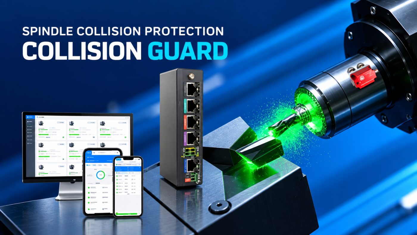
Figure 1. Spindle-area sensor and vibration monitoring screen shown in the product demonstration
What this technology can and cannot do
The system is best described as vibration-based collision monitoring or abnormal-event detection. It may help shorten the time between an unusual vibration event and operator or machine response. It cannot guarantee that a collision will be prevented, and it should not replace correct setup, collision simulation, guarding, or the machine builder’s safety functions.
From vibration signal to alarm
The demonstration presents a state-aware workflow. Instead of treating every vibration level as abnormal, it shows the system distinguishing machine conditions such as rapid traverse, cutting, stopping, and tool change, then comparing measured vibration with learned or configured limits.
Stage | Function shown in the video | Integration question |
1. Sense | A sensor near the spindle or spindle assembly measures vibration during operation. | Confirm mounting point, orientation, attachment method, cable routing, and environmental rating. |
2. Establish normal profiles | The video says the system learns vibration values for different machine states over a period of 7–10 days. | Confirm what is learned, how long it takes, and what triggers re-learning after a program, tool, or setup change. |
3. Detect deviation | Live vibration traces are compared with state-specific alarm thresholds. | Test thresholds against normal variation, tool changes, coolant, workholding, and representative cuts. |
4. Notify or signal | The demo shows an alarm display and a machine-side signal path. | Identify whether the output is an alert, feed hold, controlled stop, or another defined action. |
5. Review the event | The demo shows event records and optional video around an abnormal event. | Confirm timestamps, video window, retention, access rights, and machine/program context. |
Why machine-state baselines matter
A rapid traverse, tool change, interrupted cut, chip impact, or change in workholding can create vibration that differs from steady cutting. A single global threshold may therefore produce nuisance alarms or miss an event. Baselines should be developed for the real machine, spindle, tooling, workholding, programs, materials, and operating states. Significant process changes should trigger a review of the thresholds.
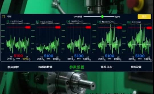
Figure 2. Vibration channels and limit lines shown in the source interface (Chinese-language UI); values are not transferable settings
Alarm response and event traceability
An alarm is useful only when the next action is clear. The video shows a red alarm screen and indicates that a signal can be sent to the machine. Before integration, define who receives the alert, how the machine responds, whether the operator must acknowledge it, and how the machine is safely reset.
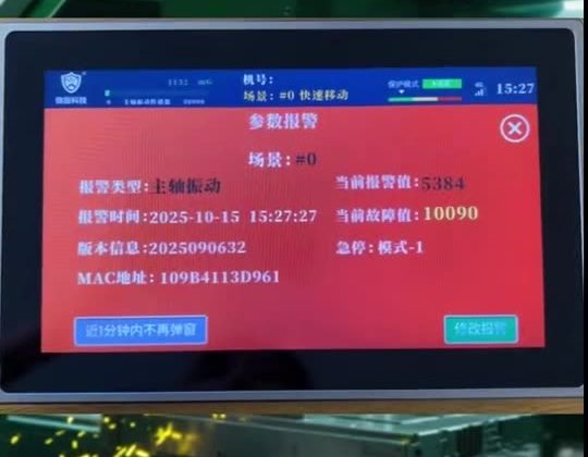
Figure 3. Example alarm display Figure
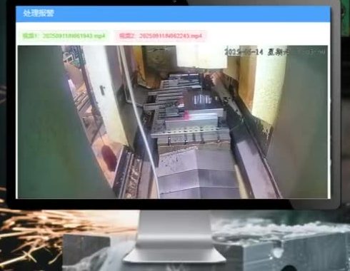
4. Event video archive shown in the demo
The video also depicts optional camera support and playback around an abnormal event, described in its captions as three minutes before and after the event. Treat this as a supplier-described feature until the recording window, trigger logic, retention period, and time synchronization have been confirmed on the actual installation.
Machine-side integration requires proof
Do not infer that an alarm automatically stops the spindle or prevents injury. The complete response path may include sensor sampling, signal processing, controller logic, output hardware, the CNC or PLC scan, drive response, and machine deceleration. A fast detection figure at the sensor does not establish the end-to-end stopping time.
Any machine-stop output should be reviewed with the machine OEM and the system supplier, then tested under controlled, non-damaging conditions. The monitoring system should not be represented as a safety-rated protective function unless its safety rating, architecture, and integration have been documented and assessed for the machine application. Machinery risk assessment and risk reduction should remain part of the overall design process (see ISO 12100:2010).
Commissioning checklist and claims to verify
Commissioning area | Checks before production use |
Mechanical installation | Use the supplier-approved location and mounting method. Check stiffness, orientation, environmental exposure, moving-axis cable routing, and clearance. Do not attach a sensor to a rotating component unless explicitly designed and rated for it. |
Baseline capture | Record normal vibration for idle, rapid traverse, tool change, and representative cutting states. Include normal process variation and document the machine, program, tool, fixture, and material. |
Alarm tuning | Set limits by state where supported. Check nuisance alarms and missed detections with representative non-damaging tests; do not validate by deliberately crashing the machine. |
Machine response | Document the exact output signal, CNC/PLC interface, stop strategy, reset behavior, fail state, and end-to-end response. Coordinate changes with the OEM. |
Records and network | Verify timestamps, event/video retention, user permissions, remote access, and data ownership. Review network and cybersecurity requirements before enabling remote monitoring. |
Operator procedure | Define who responds, what to inspect, when to resume, and how alarms are logged. Train operators not to bypass or casually raise thresholds. |
Performance statements in the video
Claim shown | Evidence issue | Publication treatment |
Response time | The video shows 0.25 ms on a promotional graphic and 0.5 ms in a caption about sending a stop signal. | These figures conflict and may describe different stages. Do not publish either as verified end-to-end stopping time without supplier documentation and machine-level tests. |
Learning period | The caption describes 7–10 days of learning vibration values across machine states. | Confirm the required production conditions, learning method, and re-learning criteria. |
Other percentage claims | The video displays percentage-based benefits without a defined baseline, test method, sample size, or operating conditions. | Exclude them from customer-facing claims until supporting evidence is available. |
Practical takeaway
Vibration monitoring can be considered as an auxiliary condition-monitoring layer for high-value or unattended CNC operations. Its practical value must be demonstrated on the target machine and process: reliable state baselines, acceptable false-alarm behavior, a proven machine response, and a clear operator procedure. For an application review, provide the machine model and control, spindle arrangement, operation types, intended response, and any integration constraints.
Reference: ISO 12100:2010, Safety of machinery — General principles for design — Risk assessment and risk reduction. Confirm the applicable edition and local requirements for the machine and market.
Send us your drawing or sample — our engineers review material, tolerances and cycle time, and reply with a machine & process recommendation.
Discuss Your Part →