Automated Turning of Automotive
Welding Locating Pins
A vibration feeder and rear-spindle feed path reduced the reported cycle from about 20 seconds to 10 seconds per part.
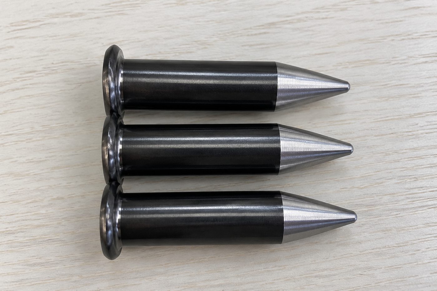
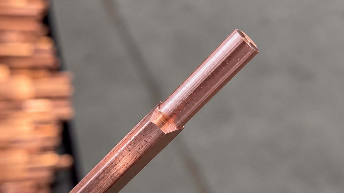
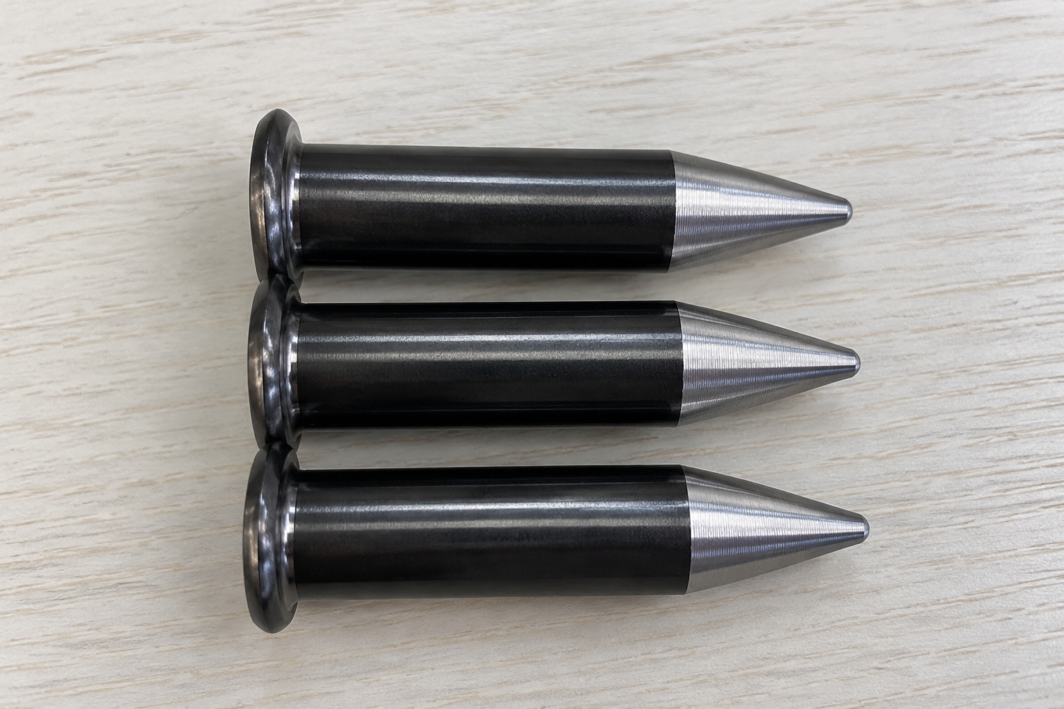
Finished locating pins with turned positioning tips
WORKPIECE | MATERIAL | KEY OPERATION | REPORTED CYCLE |
Automotive welding locating pin | 45 steel | Turned locating tip | ~20 s → ~10 s / part |
Project overview
The customer needed a repeatable way to machine the locating tip on a small steel pin used in automotive welding operations. The previous process relied on manual loading at conventional CNC lathes. SIPENG reorganized the feed, clamping, turning and discharge sequence around a dedicated automatic machine.
The reported cycle fell by approximately 50%. The project also identified the next process opportunity: reduce cutting time by changing the incoming blank geometry, then validate the result through machining trials.
01 Starting process and production constraints
The original process used a conventional CNC lathe. An auxiliary sleeve was fitted over the workpiece before an operator loaded it into the machine. The shop reported operating two lathes per operator, with a cycle of about 20 seconds per part.
· Manual loading and part handling made the cycle dependent on operator activity.
· The auxiliary sleeve added a handling step and made automatic transfer less straightforward.
· The cylindrical blank carried substantial stock at the tip, so material removal limited further cycle-time reduction.
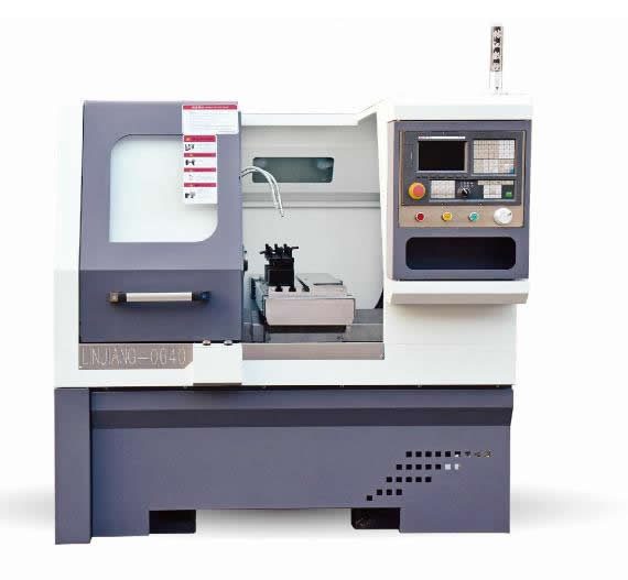
Conventional CNC lathe used in the original process
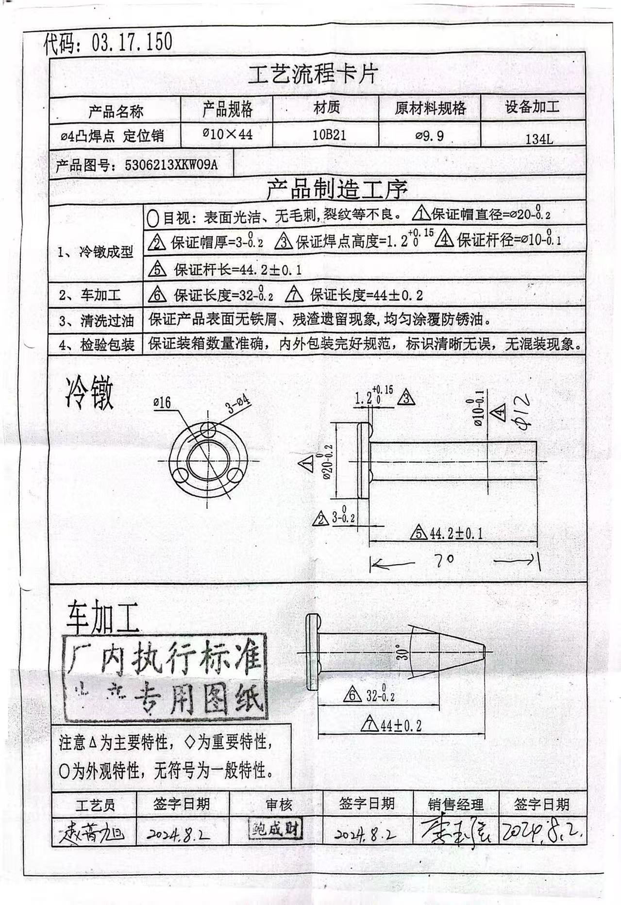
Customer part drawing supplied for process review
02 Automation concept
The new arrangement was designed around the part’s small size, repeated geometry and batch-production requirement. A vibration feeder orients and supplies the blanks; the workpiece enters from the rear of the spindle, is clamped for tip turning, then exits through the rear after machining.
1 Orient and feed | The vibration bowl presents blanks in a consistent orientation. |
2 Load and locate | The part enters through the spindle rear and is secured by the workholding arrangement. |
3 Turn and discharge | The locating tip is turned in one clamping; the part is released and discharged to continue the cycle. |
03 Machine arrangement and workholding
The dedicated machine combines automatic orientation, rear-end feeding, workholding, turning and discharge in a repeatable sequence. The intent is to shorten the non-cutting portion of the cycle by keeping the part path direct and coordinating each movement with the machining cycle.
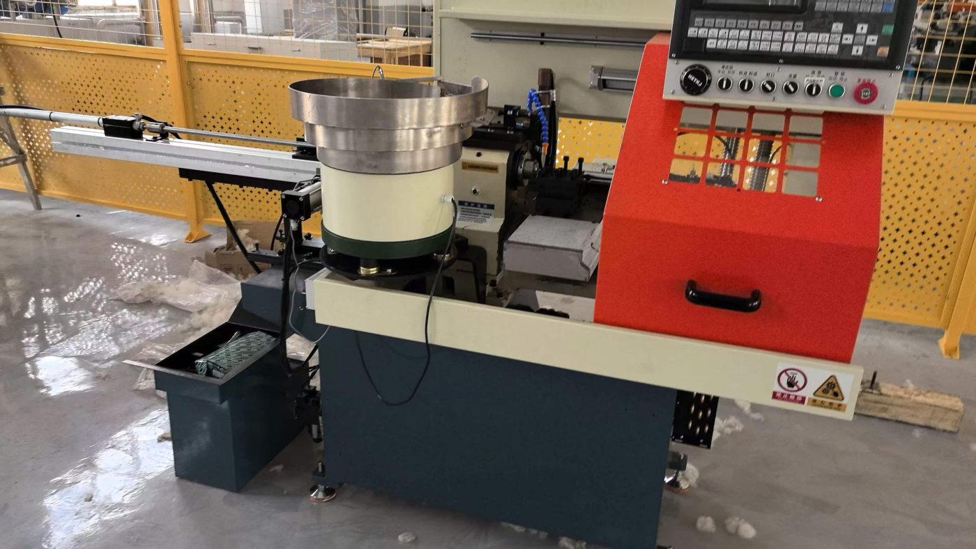
Automatic feeding and turning machine arrangement
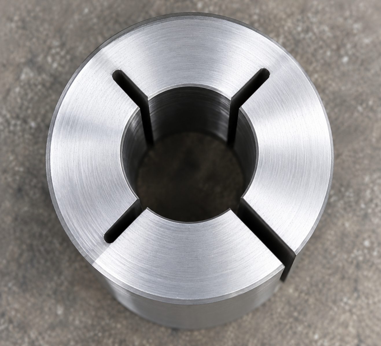
Workholding collet / clamping interface
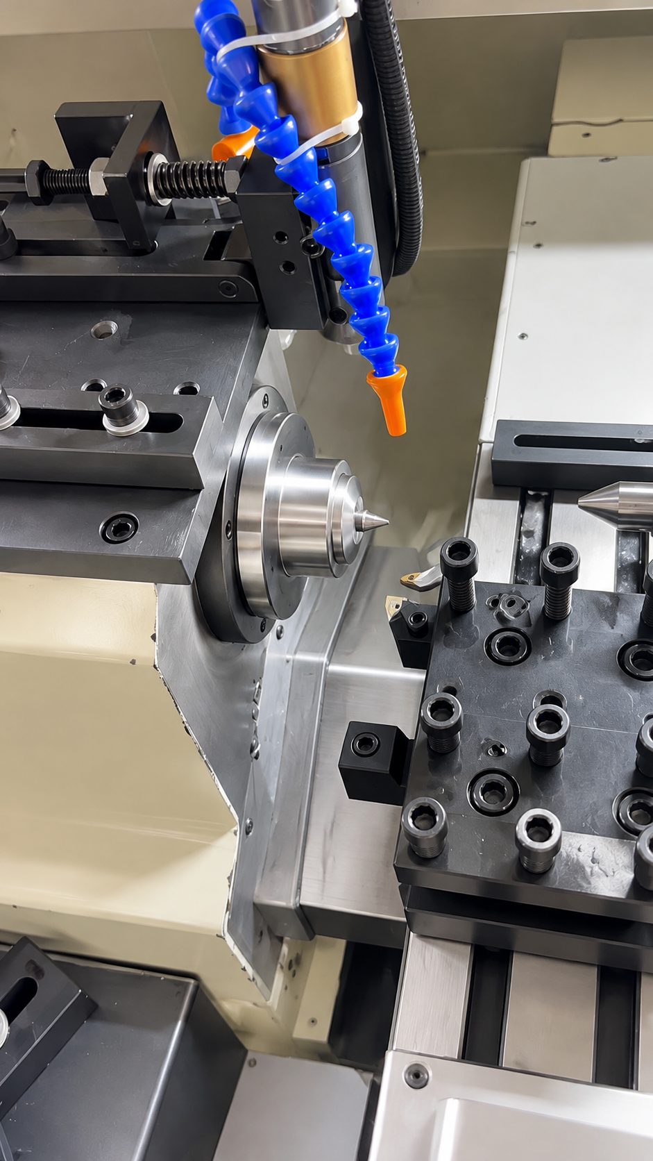
Tooling and part position in the machining area
Automatic cycle
Orient → feed from spindle rear → clamp → turn the locating tip → release → discharge. The source process record states that automatic infeed and outfeed take no more than about 2 seconds per part; the reported cutting time is about 8 seconds.
04 Cycle-time comparison
Measure | Original process | Automated arrangement |
Machine / handling | Conventional CNC lathe; manual loading with an auxiliary sleeve | Dedicated automatic machine; vibration-fed blanks |
Part transfer | Operator-assisted loading and handling | Rear-spindle infeed and rear discharge |
Reported cycle | ~20 s per part | ~10 s per part |
Cycle components | Not separately recorded | ~8 s cutting + ≤2 s infeed/outfeed |
Theoretical output* | ~180 parts/hour | ~360 parts/hour |
*Theoretical hourly output is calculated as 3,600 seconds divided by the stated cycle time. It is a cycle-capacity comparison, not a guaranteed production rate. Actual output depends on uptime, replenishment, tool changes, inspection and overall equipment effectiveness.
05 Engineering assessment and next step
Automation has already reduced manual handling and non-cutting time. With infeed and outfeed reported at no more than 2 seconds, the remaining opportunity is primarily in the approximately 8-second cutting operation.
The current cylindrical blank requires the tip to be formed by removing a relatively large amount of material. A practical next step is to evaluate a near-net preformed tip on the blank, while retaining only the finishing stock needed to meet the drawing’s dimensional and surface requirements. This could shorten the cutting path, but the cycle benefit must be confirmed with representative blanks and machining trials.
· Review blank geometry and supply method before increasing speed or feed aggressively.
· Run controlled trials to confirm tool load, process stability, tip dimensions and surface quality.
· Record validated cycle time and production conditions before making a capacity commitment.
Where this approach may apply
The same part-first review can be considered for repeat-production locating pins, dowel pins and other small turned components. The relevant comparison is the cost and time per conforming part, including handling, tooling, inspection and machine utilization.