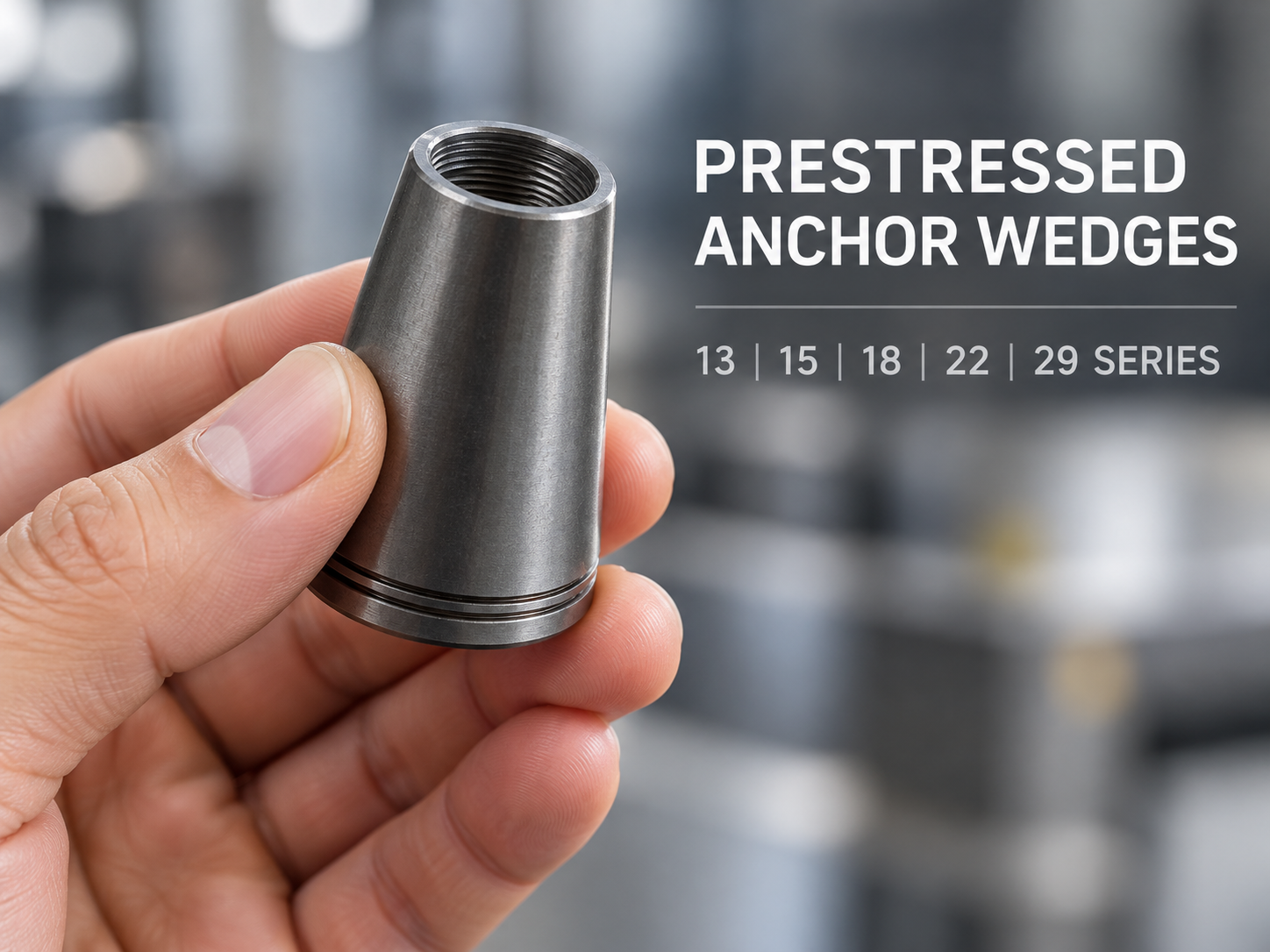
Prestressed Anchorage Wedge External Taper Machining Automation Case Study
SIPENG CNC | Engineering Application Case
This project addresses external-taper turning, an external circumferential groove and a chamfer at the small-end bore of a prestressed anchorage wedge blank. The existing process already completed these operations in one setup. The improvement added automatic feeding and a dual-channel CNC lathe to reduce manual part handling and organize continuous production. The customer reports that the machining time per part fell from about 20 seconds to about 14 seconds. Commissioning also showed that bore consistency and machining allowance in the incoming blanks directly affect feeding, clamping and stable cutting.
Part and Machining Scope
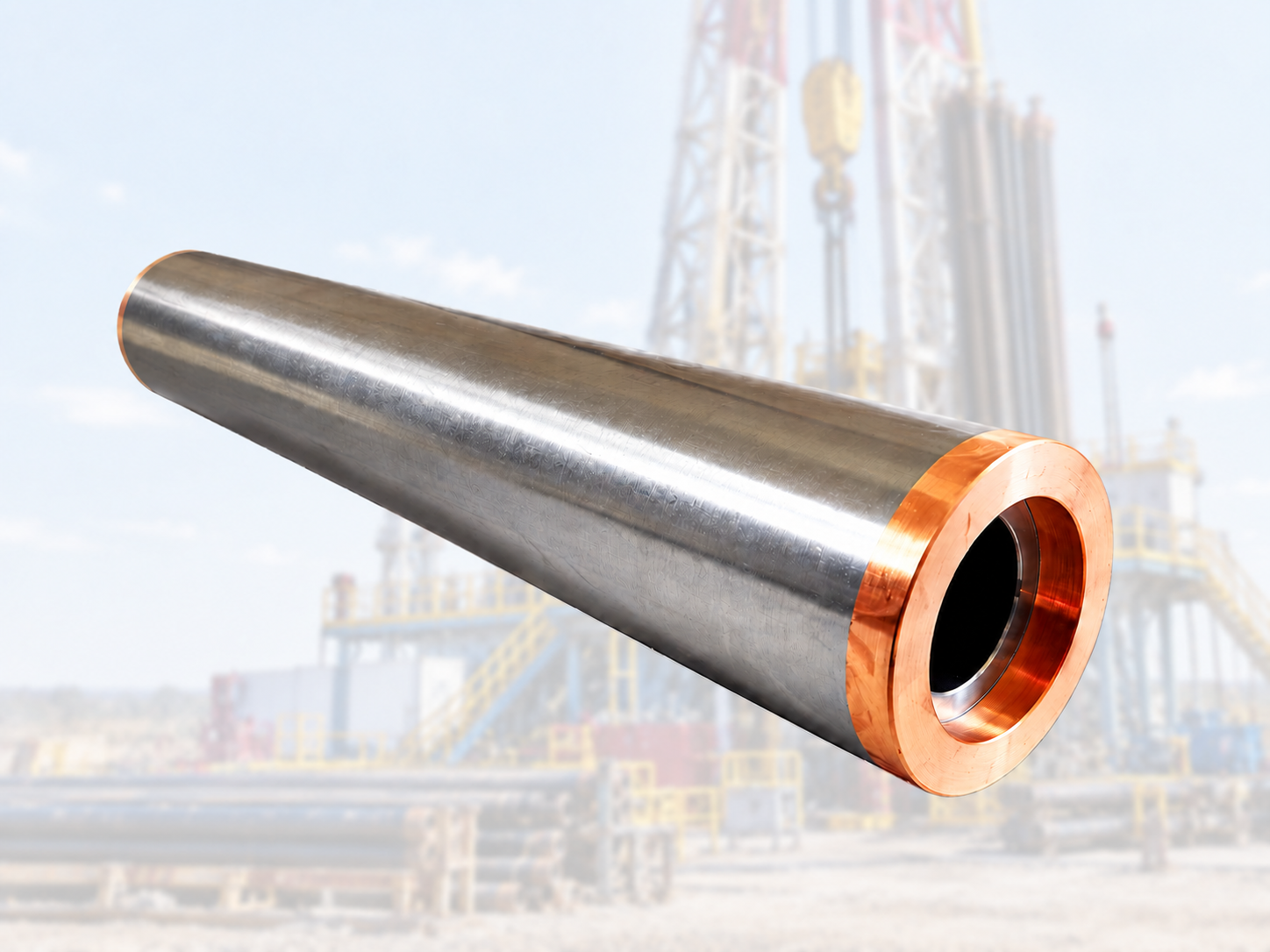
The component is used in prestressed anchorage applications, including bridges, high-rise buildings and mining. This case covers the turning operations only. Completion of this turning stage does not mean that the wedge is fully manufactured or that anchorage performance has been accepted.
The turning scope includes the external taper and associated outside-diameter surfaces, an external circumferential groove, and a chamfer at the small-end bore. The source material calls the groove a “retaining-ring groove”; its actual function and dimensions must be confirmed from the customer drawing. The drawing should define the taper angle, diameters, effective length, surface finish and datum relationship to the bore.
The source lists 40Cr and “45CrMo” among the alloy-steel materials. The exact grade and governing standard for “45CrMo” remain unconfirmed and should be checked against the customer’s material certificate. Material condition, hardness and any subsequent heat-treatment requirements should also be confirmed from the drawing and purchasing specification.
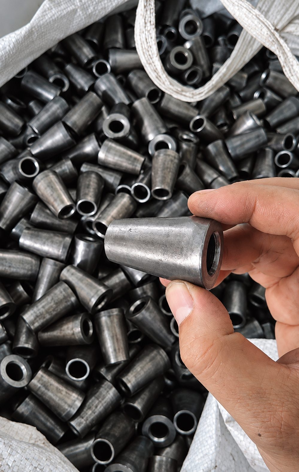
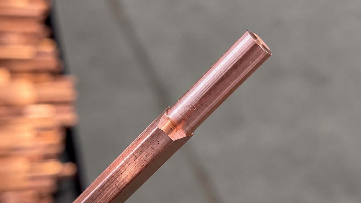
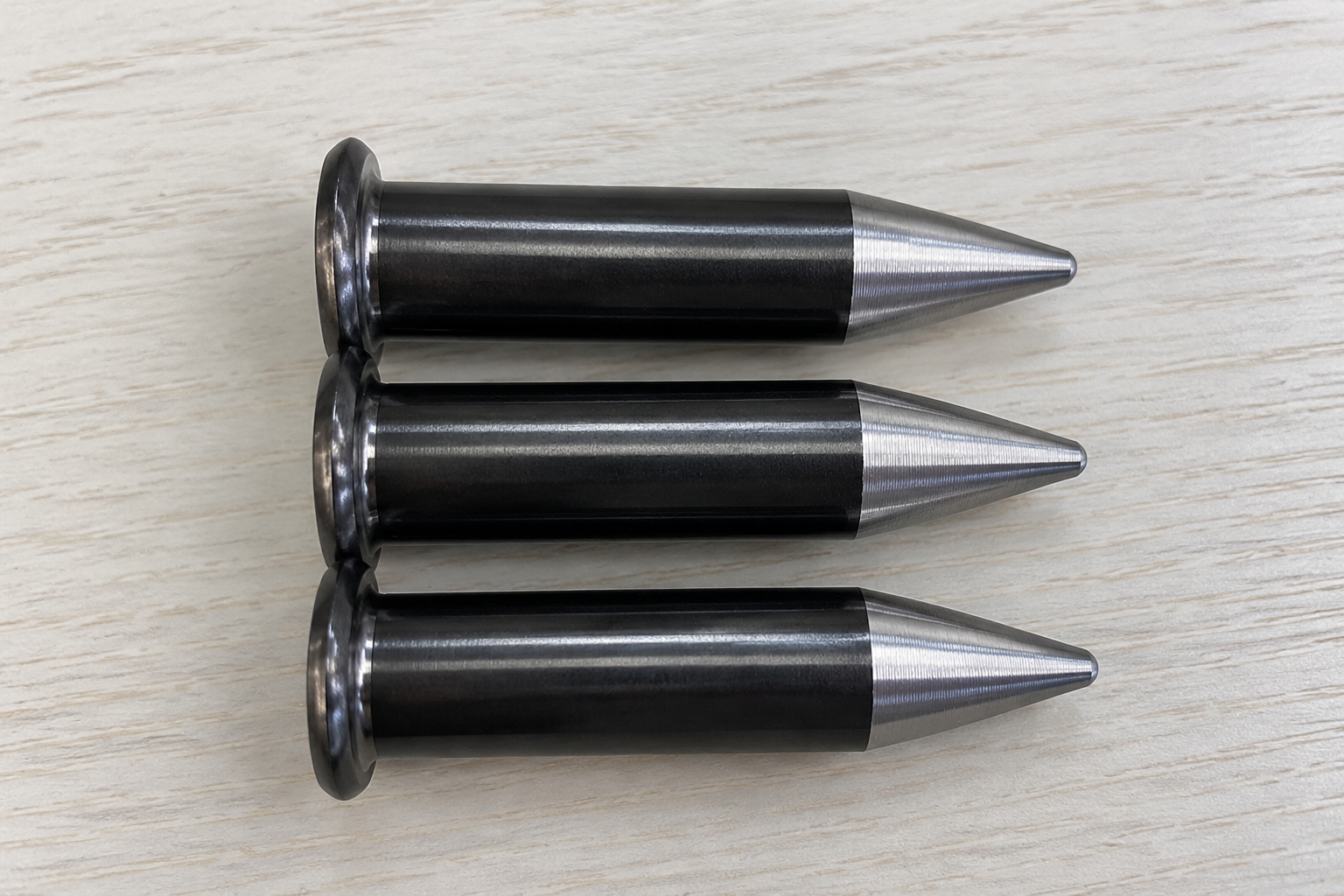
Figure 1. Incoming wedge blank
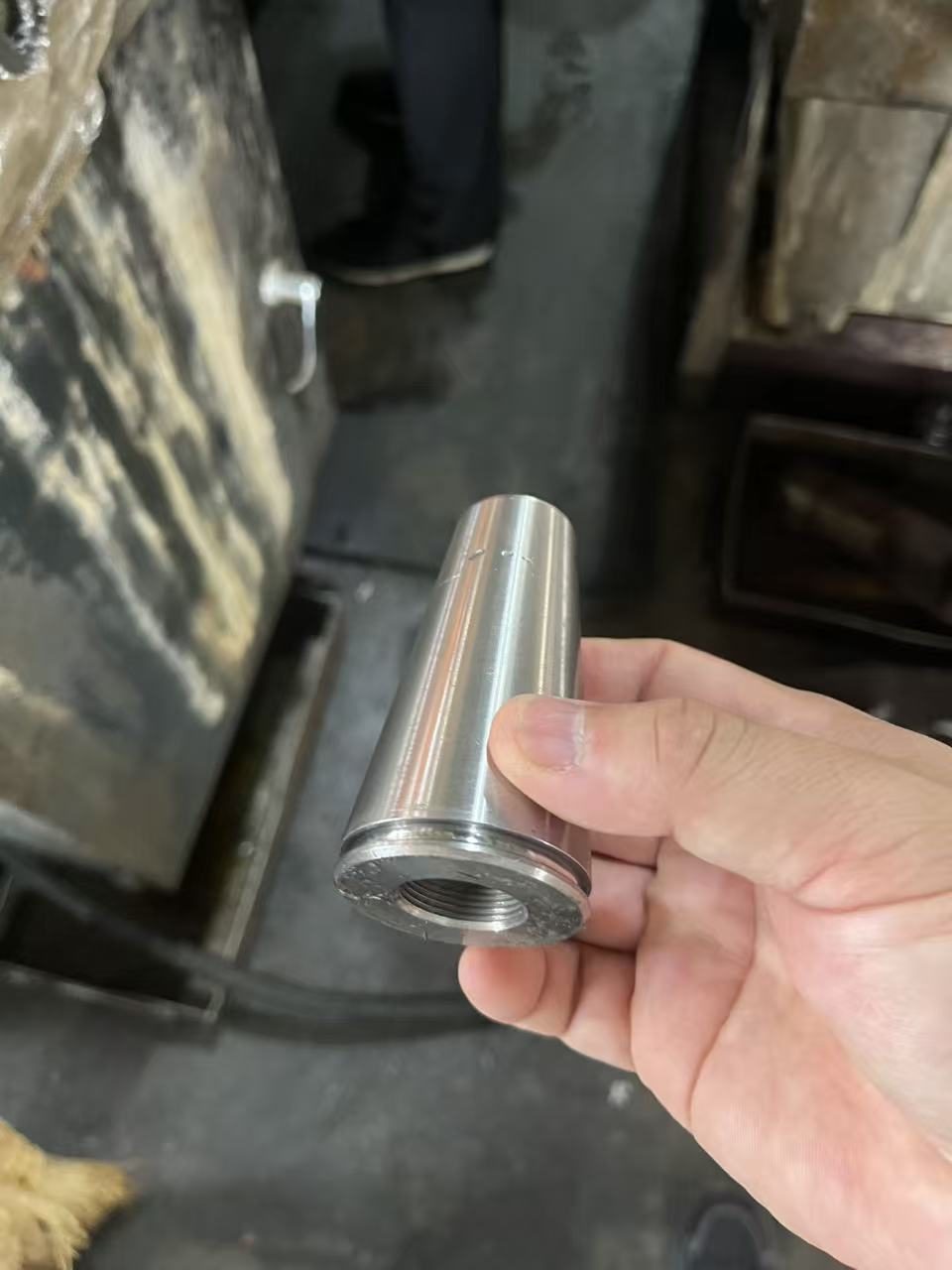
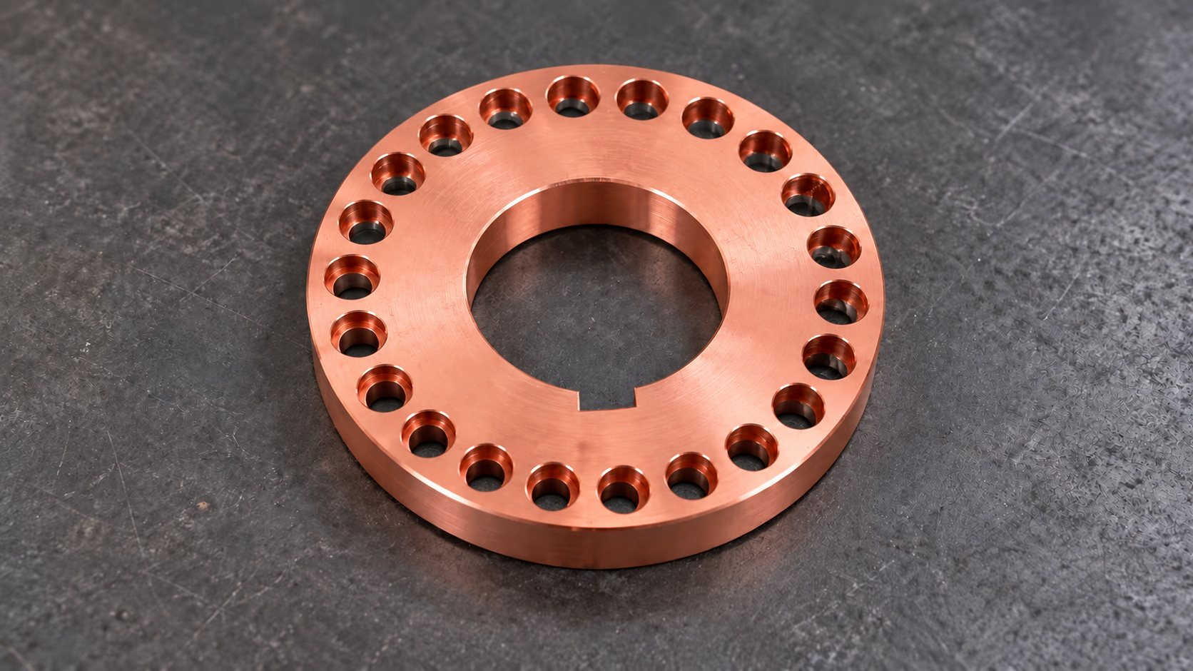
Figure 2. Wedge after turning
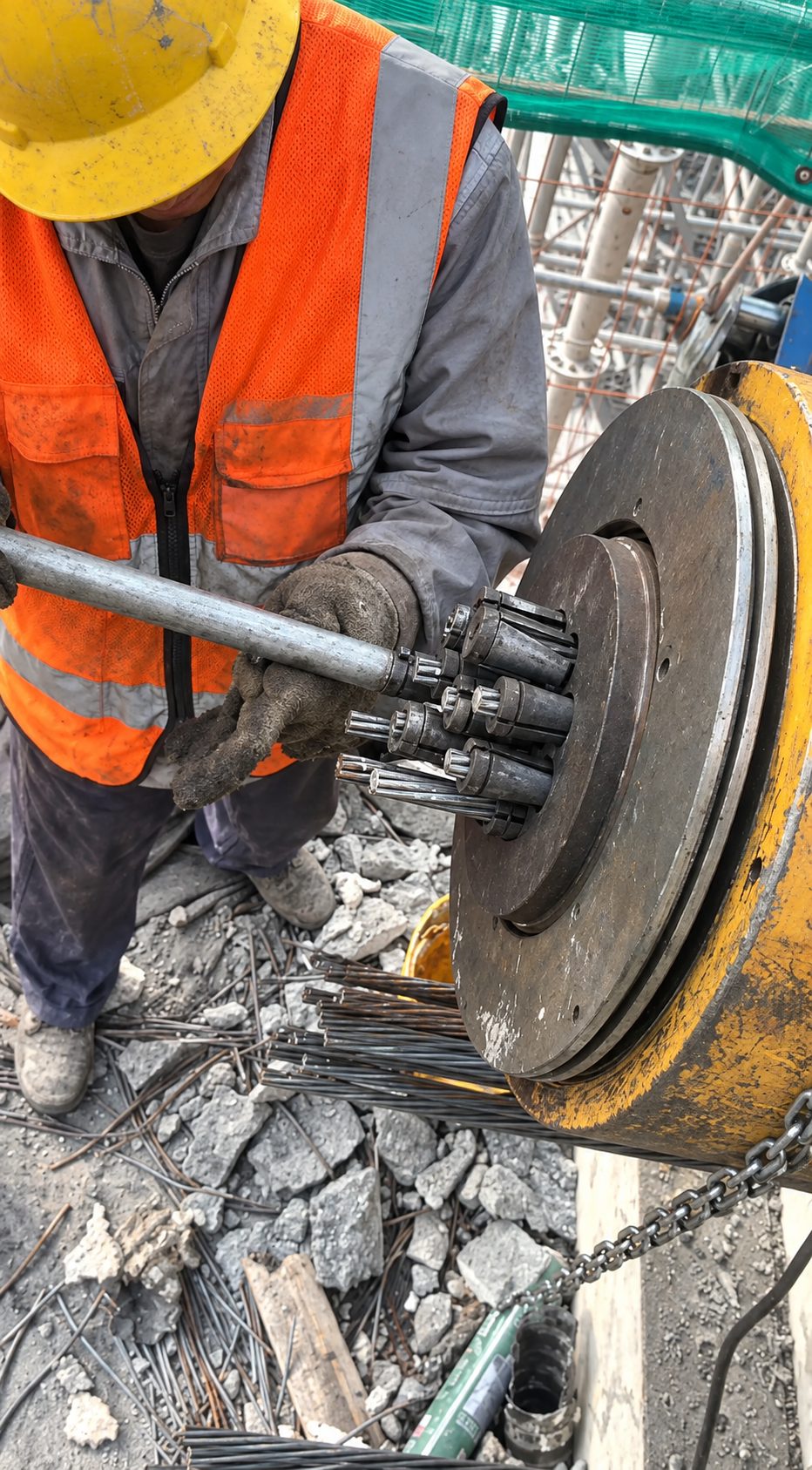
Figure 3. Prestressed anchorage application
Original Process and Main Constraints
The original process used 0640 CNC lathes, with one operator tending three machines and loading and unloading each part manually. The part was completed in one setup for this turning stage, and the customer reported a cycle time of about 20 seconds. Since the original process already completed the operations in one setup, the improvement focused on reducing manual loading and unloading, reorganizing production and increasing the potential for continuous operation.
Some blanks have an outside diameter 3–4 mm larger than the target diameter. If this is the diameter difference at the same cross-section, the corresponding radial stock is about 1.5–2 mm. For a tapered blank, the stock should be checked at several sections; the stated difference should not be treated as the cutting depth everywhere. Larger stock increases the volume to remove, cutting load and chip-evacuation demand.
The customer reported a high volume of chips and cases of chips wrapping around the workpiece and tool. Process improvement should review blank allowance, insert chipbreaker geometry, feed, depth of cut, coolant delivery and chip evacuation together. Increasing spindle speed alone is not a reliable remedy, and chip wrapping should not be attributed solely to excessive stock without checking the other conditions.
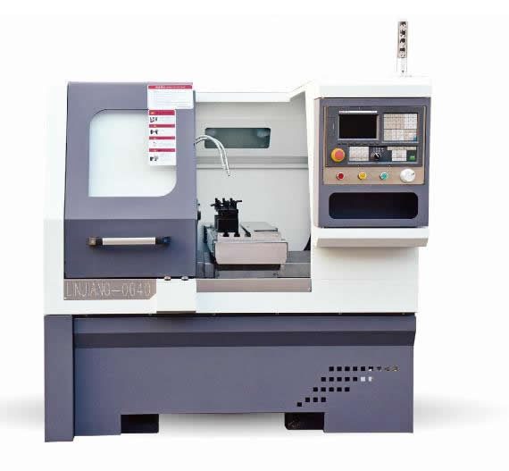
Figure 4. 0640 CNC lathe used in the original process
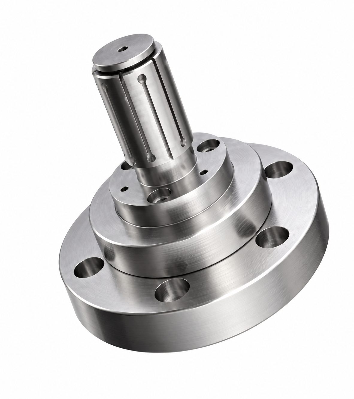
Figure 5. Internal expanding workholding fixture
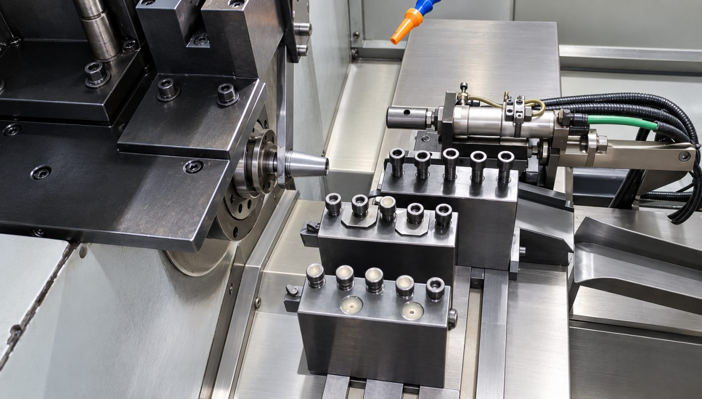
Figure 6. Original machining area and workholding arrangement
For internal expanding workholding, confirm the incoming-bore size range, effective contact length and workpiece position after expansion. Commissioning should verify both slip resistance and the risk of workpiece distortion, as well as axial location and the actual relationship between the external taper and bore. A fixture photograph does not replace setup-accuracy records.
Automatic Feeding and Dual-Channel Machining
The project added an elevating feeder so operators can replenish a batch of blanks while the machine feeds and unloads parts automatically. Blanks are lifted, oriented and transferred into the machine; finished parts are discharged automatically. The feed direction and recovery actions for a missing or jammed blank should be confirmed against the installed mechanism and control program.
The source describes the feeder as providing “automatic recognition” but does not identify how recognition is performed. This case therefore describes the function as automatic part orientation and feeding. It does not claim that the machine includes vision recognition or in-process dimensional inspection.
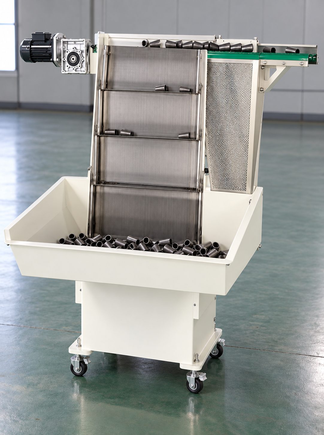
Figure 7. Elevating automatic feeder
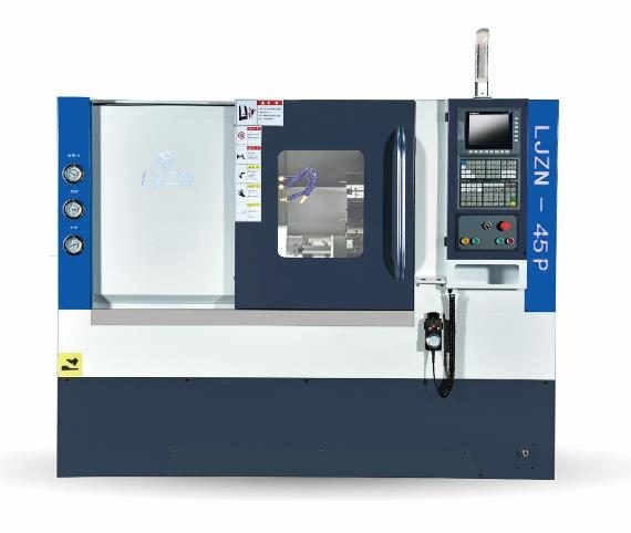
Figure 8. CNC lathe in the new process
The dual-channel configuration organizes the corresponding turret and machining actions. The channel sequence, interlocks and tool-clearance envelope must be defined to prevent interference. Whether both channels cut simultaneously and how operations are assigned must be confirmed from the actual machine configuration, program and commissioning records; the name “dual-channel” alone does not establish the source of any cycle-time improvement.
The process plan should still define workholding, the allocation of roughing and finishing, groove and chamfer operations, cutting data and retract paths for the part. Auxiliary motions and cutting time should be reduced only after clamping and chip evacuation are stable.
Figure 9. Machining area of the new process
Commissioning Findings and Blank Selection
During early commissioning with hot-forged blanks, the customer reported inconsistent bore roundness and size, unreliable feeding and selection, slipping after clamping, and limits on turning speed. These observations indicate that the tested blanks were not adequately matched to the installed feeder, fixture and cutting conditions. They should be investigated individually rather than addressed only by increasing clamping force.
With bore-based location or expansion clamping, bore variation may lead to uneven contact, positional shift or reduced effective clamping capacity. The specific cause should be verified by measuring the bore, checking contact conditions and making trial cuts. Before increasing expansion or clamping pressure, confirm the allowable workpiece distortion and fixture limits.
After several rounds of testing, the project selected cold-forged blanks as the production input for the current setup. This finding applies to the blanks, fixture and cutting conditions tested in this project. It does not mean that hot-forged blanks are generally unsuitable for machining or that every cold-forged blank can be fed automatically without qualification.
Incoming Blank Conditions for Sustained Production
Purchasing specifications should define material and hardness, bore size and form variation, overall profile and length range, machining allowance at multiple sections, burrs and surface condition. The blank must meet the feeder path, fixture clamping range and tool-load requirements. Representative lots should be trialed before release to production.
Feeder acceptance should record jams, incorrectly oriented blanks and missed feeds. Workholding acceptance should record slip and post-machining deviations. Cutting validation should check chip wrapping, tool wear and continuous-running behavior. These are proposed validation records; they do not imply that all of these inspection functions are built into the machine.
Machining Time and Output Comparison
The customer reports about 20 seconds per part for the original process and about 14 seconds for the new process. Compare these figures over the same sequence of actions and state whether loading, clamping, cutting, unclamping and unloading are included. The available information does not include a complete motion-time breakdown, so the calculations below do not establish actual shift output.
Based on 20 seconds versus 14 seconds, the time per part is 30% shorter. If both figures use the same measurement scope and the machine runs continuously, the theoretical output rate is about 42.9% higher. These percentages describe different measures; a 30% reduction in time should not be reported as a 30% increase in output.
The table uses uninterrupted production with no downtime or rejected parts. Actual good-part output must account for replenishment, tool changes, chip clearing, faults, inspection and scrap. Automatic feeding can reduce one-by-one handling, but changes to the number of machines tended by one operator and to labor cost still require shop-floor records.
Measure | Original process | New process |
Loading and unloading | Manual, one part at a time | Batch replenishment followed by automatic feeding and discharge |
Machine configuration | 0640 CNC lathe | Dual-channel CNC lathe |
Staffing | 1 operator tending 3 machines | No measured machine-tending ratio provided |
Customer-reported time per part | About 20 s | About 14 s |
Theoretical output per hour | 180 parts per machine | About 257 parts per machine |
Theoretical output per 8-hour shift | 1,440 parts per machine | About 2,057 parts per machine |
Project Conclusion and Items to Verify Before Publication
The engineering value of this case lies in matching the incoming blank, feeding system, workholding and turning process as one production system. The current setup uses cold-forged blanks qualified through trials, automatic feeding and a dual-channel CNC lathe. The customer reports a shorter time per part. Process stability and cost benefits still need to be verified with continuous-production records.
Before external publication, confirm the “45CrMo” material designation, the action scope included in the 20-second and 14-second figures, the drawing and acceptance results for the taper, groove and chamfer, and the approved incoming-blank range and actual good-part shift output. The source provides no tolerance, yield, tool-life or cost data, so none are stated here. Final machine configuration, dimensions and machining quality should be supported by the drawing, physical samples and inspection records.