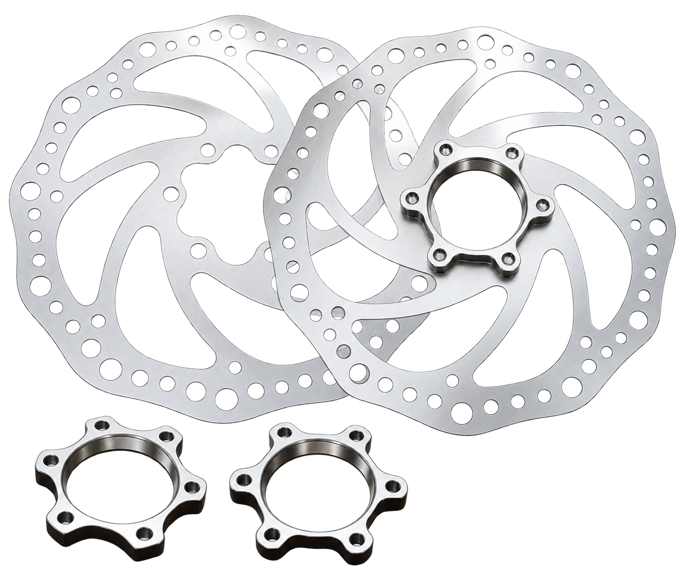
Integrated Bicycle Disc Brake Rotor
Internal Thread Machining
SIPENG CNC | ENGINEERING APPLICATION CASE
This case study covers the CNC turning operation developed for a one-piece bicycle disc brake rotor with a perforated rotor web approximately 1.8 mm thick. The operation machines the central internal thread and associated faces. The main challenge was to support the thin rotor web while locating and clamping the part securely and keeping the central machining area accessible.
After several fixture revisions, the customer reported that the operation could be completed in one setup, with an approximate cycle time of 18 seconds per part. The timing boundaries were not specified; the figure should therefore be read as a customer-reported result for this turning operation, not as the total manufacturing time for the rotor.
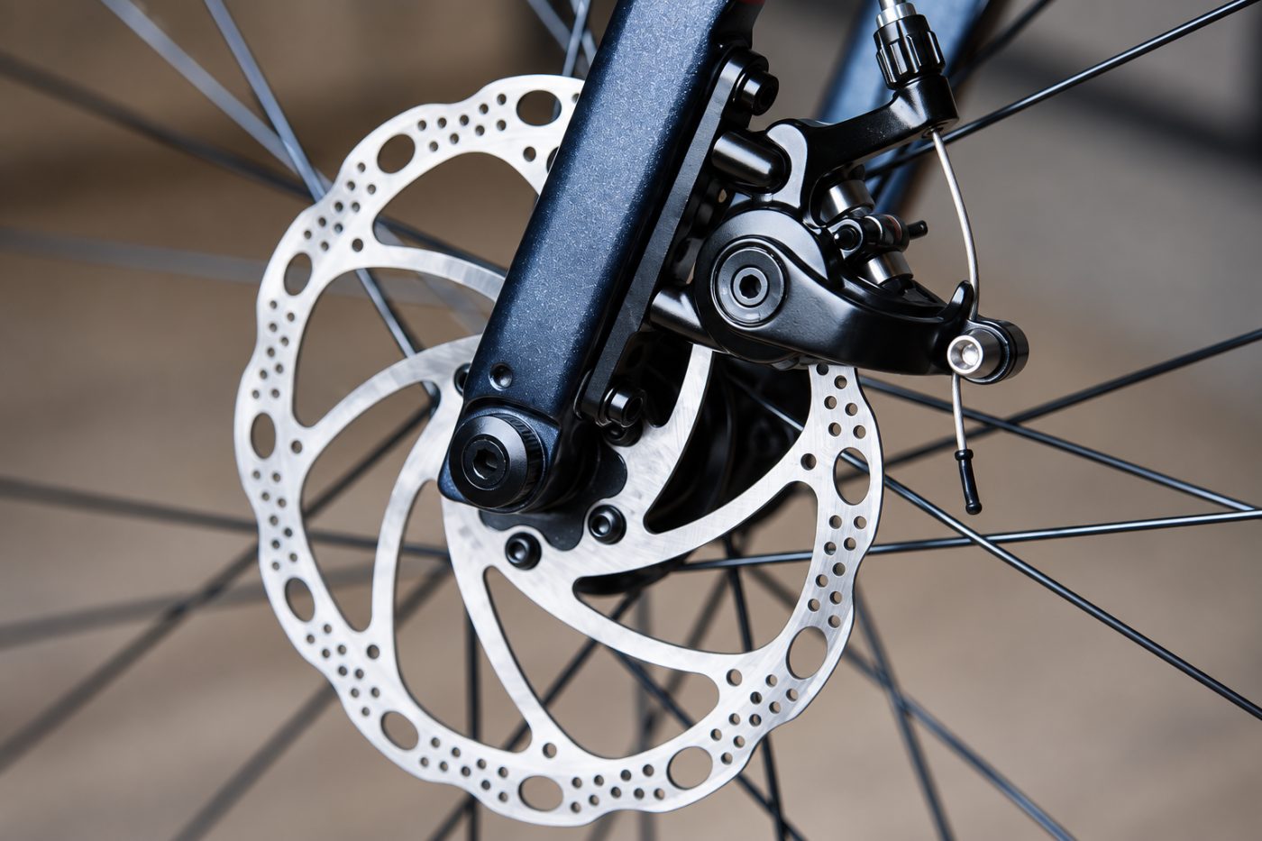
Figure 1. Disc brake rotor in service
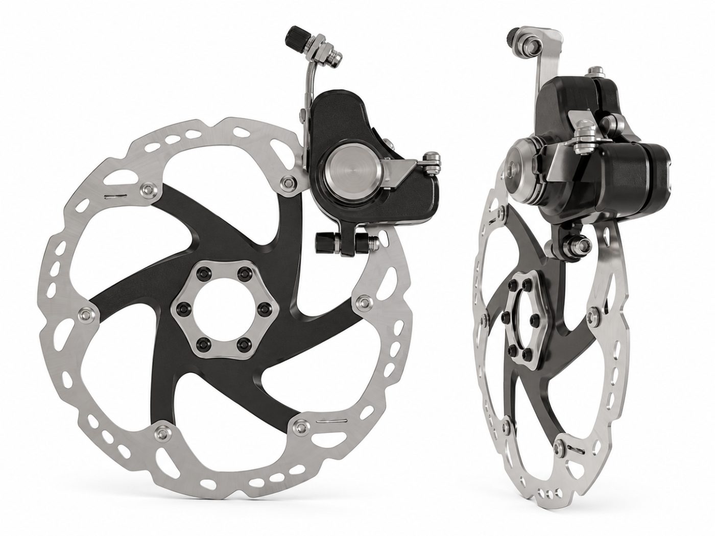
Figure 2. Disc brake assembly
Part and machining objective
The original design used a separate aluminum-alloy center carrier bolted to the disc rotor. The customer reported instances of stripped threads, loose screws, or screws that had not been fully tightened, followed by movement between the carrier and rotor. No failure-analysis records were supplied, so these reports do not establish a single root cause.
The revised design integrates the center connection with the rotor and adds an internal thread at the center. This case addresses the turning process for that design. “Rotor” refers to the rotating disc; it does not refer to the friction pads in the brake caliper.
Design change and process scope
The change removes the separate carrier-to-rotor screw assembly from the described design. The source material does not document blank production, heat treatment, or all upstream and downstream operations. The single setup described here applies only to the CNC turning operation and should not be interpreted as a one-step manufacturing route for the complete product.
Comparison | Original split design | One-piece design in this case |
Connection | Rotor and aluminum-alloy carrier joined with screws | Center connection integrated with the rotor |
Operations described | Cut aluminum stock, deburr, tap the carrier, then assemble with six screws | Load the one-piece blank; turn the internal thread and related faces |
Primary process concern | Thread condition and consistency of screw assembly | Thin-web support, clamping distortion, and central thread quality |
Time basis | Original material includes carrier work and assembly | Approximately 18 seconds reported for this turning operation; timing scope unconfirmed |
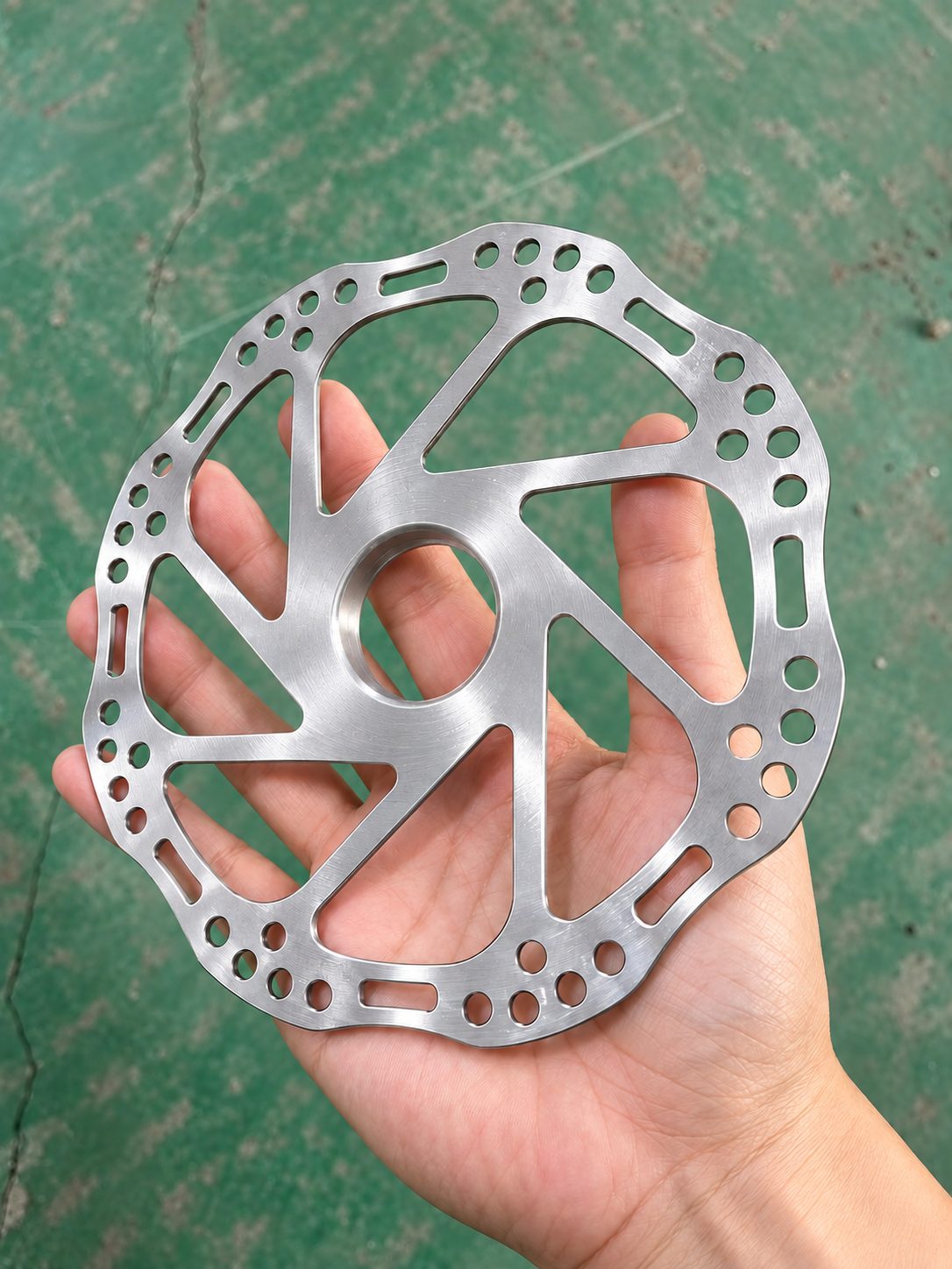
Figure 3. One-piece rotor blank shown in the source material
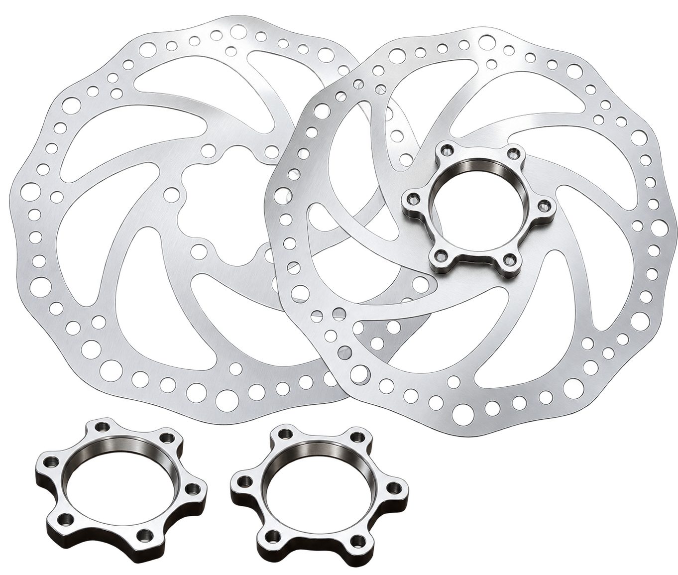
Figure 4. Rotor and center components shown in the source material
Any change to the structural design still requires validation against the customer’s design and service requirements. The machining case documents how the turning operation was supported; it does not replace product-level design or durability validation.
Machine selection and dedicated workholding
A CNC lathe was selected with a dedicated fixture for the disc-shaped workpiece. Selection must provide adequate access to the center bore and thread, a clear tool approach and retract path, and a suitable interface for mounting the fixture. The source does not identify the final machine model or configuration, so no spindle specification or automatic loading capability is claimed here.
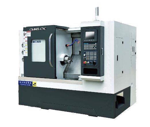
Figure 5. CNC lathe shown in the source material
Supporting a thin, perforated rotor web
At approximately 1.8 mm thick, the rotor web is both thin and perforated. Localized clamping can make it difficult to achieve secure holding without distorting unsupported areas. The fixture therefore needs to separate the functions of locating, supporting, and clamping, with support beneath each clamping region and a consistent clamping sequence.
The customer reported outer-diameter consistency within 0.05 mm. The source does not define whether this refers to batch variation, a diameter tolerance, or a roundness measure. It cannot be treated as a stated concentricity or fixture repeatability value. The actual locating datum must be confirmed from the drawing, the edge geometry, and trial setup results.
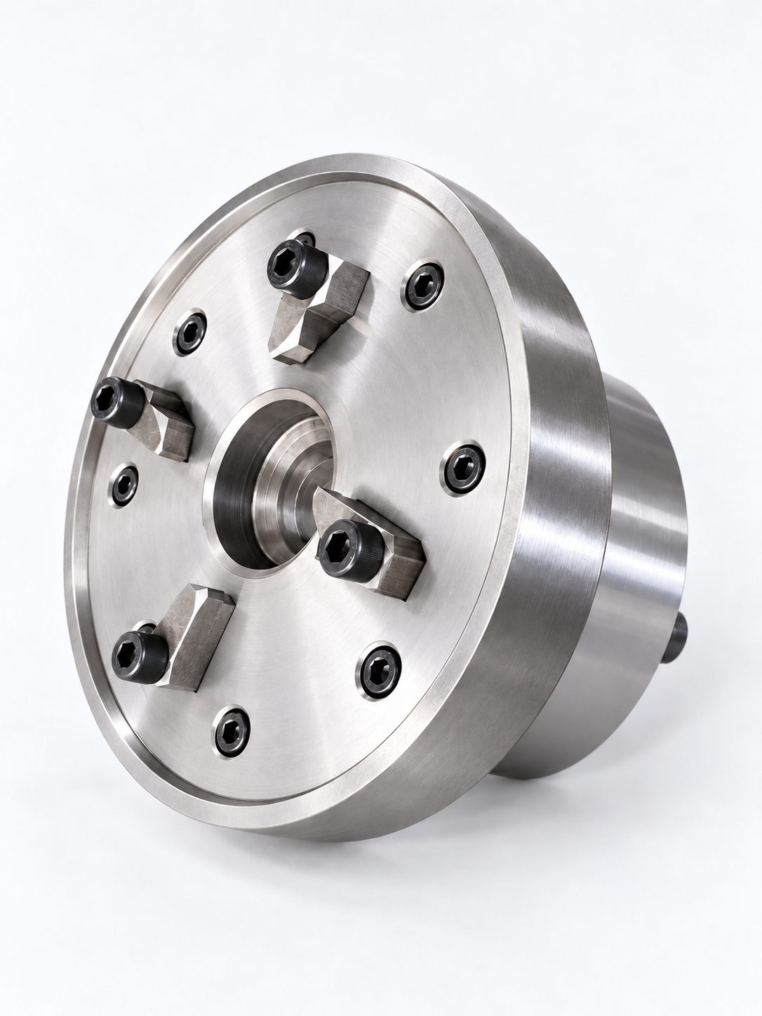
Figure 6. Dedicated disc fixture after multiple design revisions
The fixture shown uses a disc-shaped support body and distributed hold-down points. The design intent is to support the work beneath the clamps, maintain consistent contact, and leave the central bore and face-machining area open. Final locating dimensions, clamping order, and clamping force must follow the released fixture drawing and setup records.
One setup for the central machining operation
Loading and clamping
Clean the workpiece and fixture contact surfaces before loading. Seat the blank against the defined locating features, then apply the specified clamping sequence. Burrs or chips on the datum and support surfaces can prevent full seating and affect the resulting position or shape.
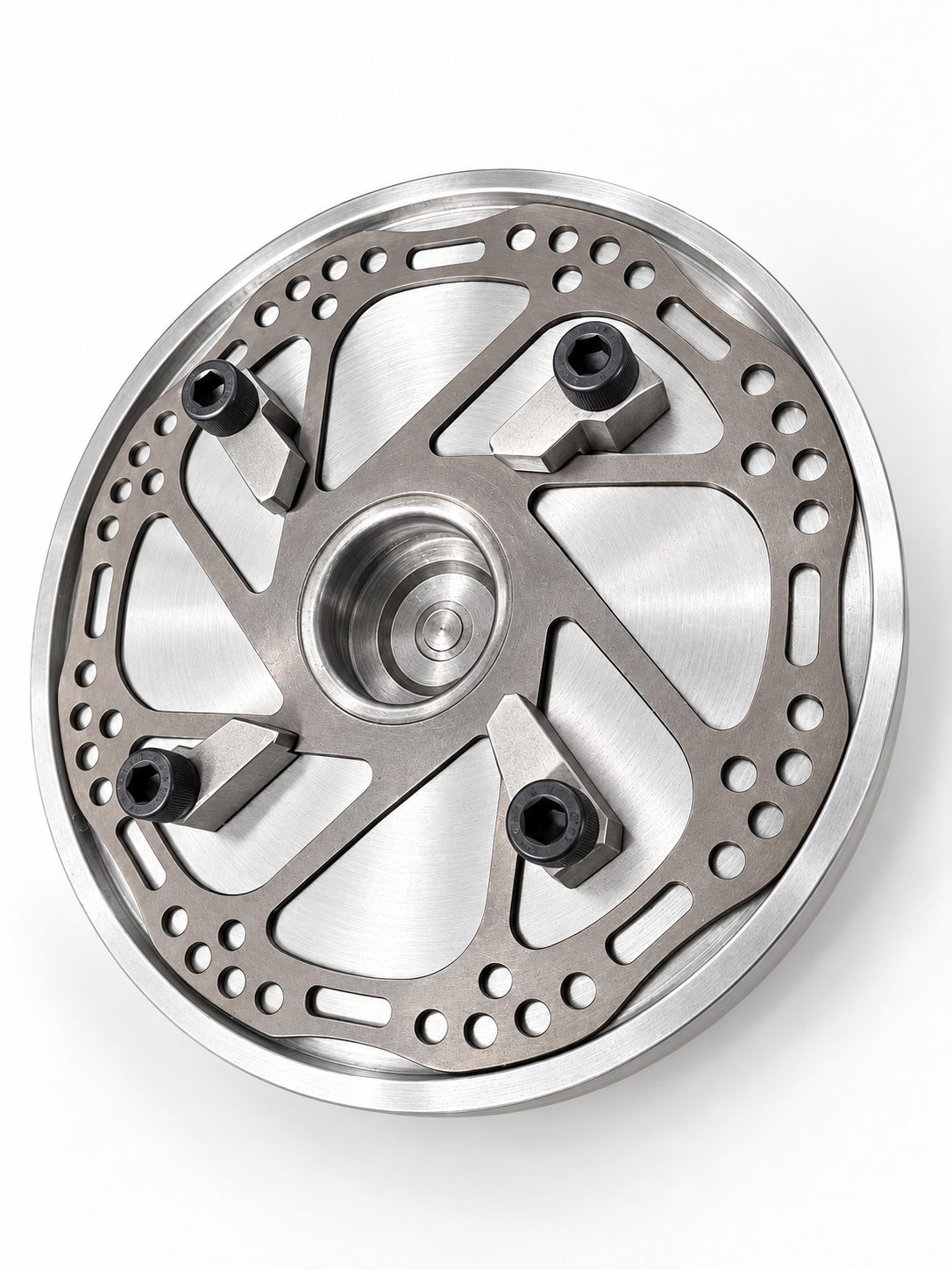
Figure 7. Rotor blank mounted on the dedicated fixture
Turning sequence and process checks
The reported setup completes the relevant faces and the central internal thread without releasing and re-clamping the workpiece. The actual operation order depends on the condition of the threaded bore, face stock allowance, and available tool access. The source did not provide the CNC program, tooling, or cutting data, so no toolpath or cutting parameters are specified.
During prove-out, verify clearance between the tools and hold-down hardware. Check for part movement, vibration, or local lift. Confirm that the fixture is suitable for the intended rotational conditions and spindle speed; do not raise speed solely to shorten the cycle.
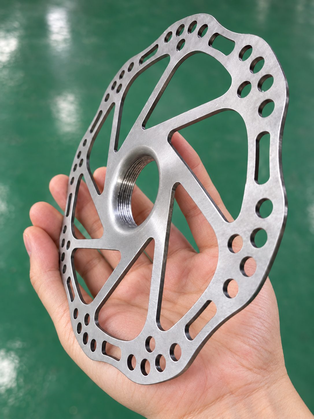
Figure 8. Finished rotor shown in the source material
The approximately 1.8 mm dimension refers to the rotor web; it does not establish the effective thread length. Verify the thread engagement length from the center geometry and customer drawing. The center-section thickness, transition radii, and face stock cannot be established from photographs alone.
Inspection, reported result, and validation items
Thread and thin-part inspection
The source calls for thread inspection with a go/no-go gauge. Use a gauge that matches the specified thread size, hand, and tolerance class and is within its calibration period. Apply the applicable inspection method; a go gauge entering the thread is not, by itself, a complete acceptance decision.
Inspect after unclamping, cleaning, and deburring. Check effective thread length, the thread entry, and machined face condition. Gauge inspection does not replace checks for rotor flatness, assembled face runout, or other drawing requirements. Because the web is thin, compare the free-state shape after unclamping with the required acceptance criteria; clamping may mask distortion. The drawing must define the inspection items and allowable limits.
Customer-reported result
After the workholding issue was addressed, the customer reported an approximate 18-second cycle time per part and completion of the described turning operation in one setup. The source does not state whether the time includes manual loading, clamping, unclamping, part removal, or inspection. It also provides no baseline cycle time, accepted output per shift, tool-change data, or defect-rate comparison. No percentage productivity gain or cost saving can be substantiated from the available information.
Technical details to confirm before publication
Material | The source records “40CrMo.” Confirm the exact grade, governing standard, and hardness/heat-treatment condition. |
Thread | Confirm nominal size, pitch, hand, tolerance class, and effective thread length from the released drawing. |
Outer-diameter figure | Define what the customer-reported 0.05 mm consistency represents and how it was measured. |
Original fasteners | The source refers to six screws and notes M6; verify the specification against the drawing or physical part. |
Cycle time | Define start/stop points and whether handling, clamping, and inspection are included. |
Final quality evidence | Confirm post-unclamping inspection results and the applicable drawing tolerances. |
Case takeaway
The core of this application is the dedicated support and clamping fixture. It enables the thin, perforated one-piece rotor to be located and held for central thread and face turning in one setup. The machine performs the cutting operation; the fixture controls how the part is supported and restrained. Final process capability and product acceptance remain dependent on the released drawing, prove-out data, and inspection results.