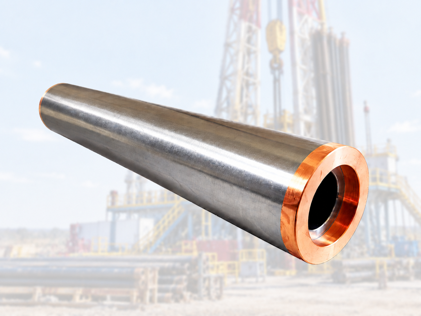
ESP Motor Rotor Assembly Outer Diameter Turning Case Study
This case study addresses three issues in turning the outside diameter of an electric submersible pump (ESP) motor rotor assembly: a visible witness mark at the transition between two cuts, repeated workpiece alignment, and impact damage during in-process handling. SIPENG CNC developed a lathe, internal-bore clamping, and storage-rack approach intended to machine the target OD continuously in one setup and protect the finished surface during handling.
Workpiece and Machining Requirements
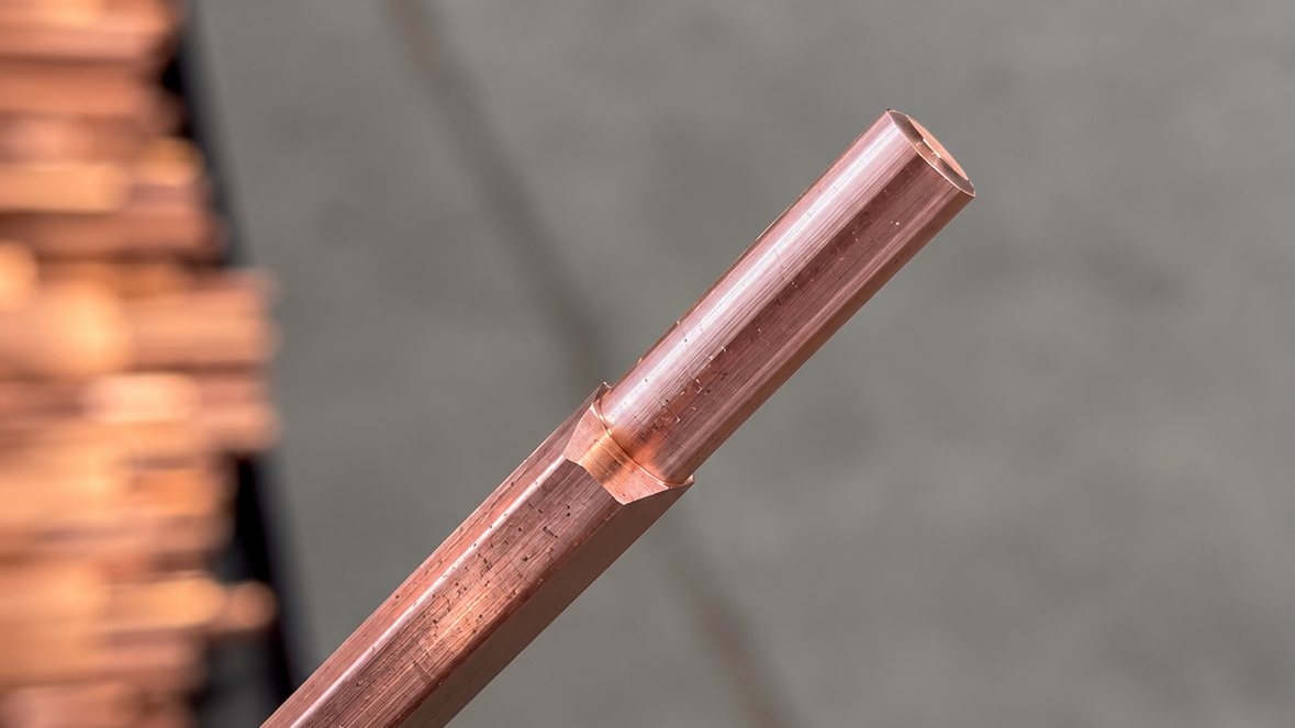
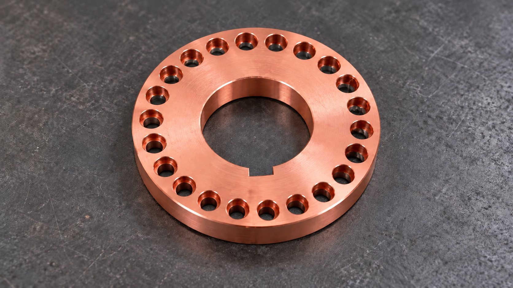
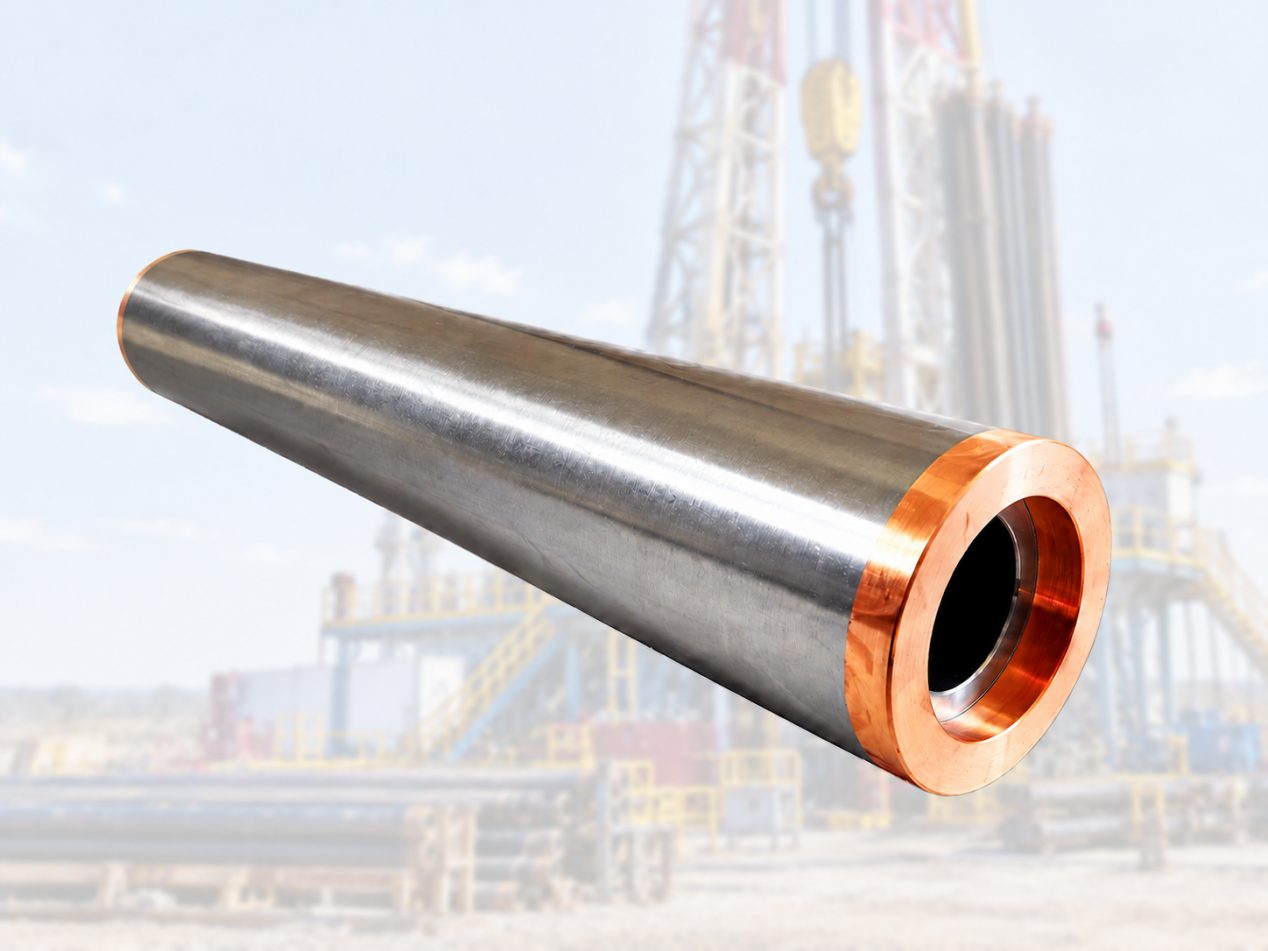
The rotor core is formed from stacked electrical steel laminations. Twenty-two copper bars pass through the core, and copper end rings are fitted at both ends. The assembled rotor OD is then turned to meet the required outside-diameter and related geometric tolerances. The machining target is the OD of the complete rotor assembly, not the holes in the copper end rings or the copper bars individually.
The customer also specified a 0.02 mm accuracy requirement, but the available information does not identify the controlled characteristic. The part drawing and inspection plan must define the characteristic, datum, and measurement method. OD size tolerance, concentricity, and radial runout are distinct requirements and must not be treated as interchangeable.
Previous Process and Quality Challenges
The original process used a conventional flat-bed CNC lathe. A manually operated three-jaw chuck held one end of the workpiece, while a live center supported the other. The operator turned approximately half of the OD, transferred the workpiece to a second machine, reversed the setup, and machined the remaining section.
Because the process required two setups, each operation involved a separate locating and alignment step. The second setup required careful runout correction and control of the transition between the two machined areas. The customer reported a visible witness mark near the middle of the OD, where the two cuts meet and a reported pass rate of approximately 85% under the original process. This figure reflects the customer’s production feedback; it was not measured in a controlled, like-for-like trial.
The main process difficulties were obstruction of the target OD by the clamping arrangement and the need to re-establish the machining reference after reversing the workpiece. Changing the machine-bed configuration alone would not resolve these issues. The workholding method and tool-access envelope also had to be addressed.
Surface Protection During Work in Process
Raw, partially machined, and finished rotors must be stored and moved between operations. The customer reported that the original storage and transfer method exposed the parts to impact damage. Once the OD has been turned, dents or scratches from handling can compromise the delivered surface condition.
The proposed process therefore includes protection throughout loading, transport, and storage. Each rotor should have an individual position, with supports that avoid direct metal-to-metal contact on the machined surface. Separate locations for raw parts, work in process, and finished parts also help prevent mix-ups and contact damage. Final inspection alone cannot prevent handling damage.
Lathe Configuration for Continuous OD Turning
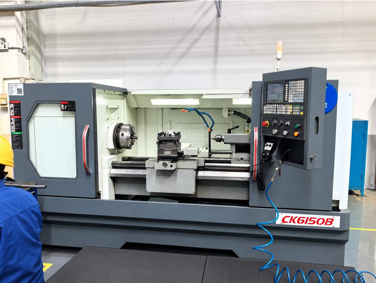
SIPENG CNC proposed a slant-bed CNC lathe with internal-bore workholding at the spindle end and a bore-matched support at the opposite end. This arrangement keeps the target OD accessible to the cutting tool. The process objective is to turn the complete target OD continuously in one setup, removing the workpiece reversal and mid-section transition between the two cuts used in the original process.
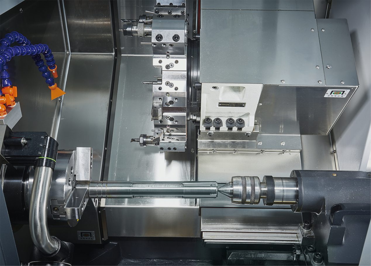
Machine selection should be based on workpiece length, swing diameter, mass, tool travel, and support conditions. For this application, the machine must cover the full target OD while the clamping and support components leave a clear path for the tool. The available machining envelope and axis travel must be verified against the actual part and fixture drawings.
Reducing the number of setups can reduce error sources associated with repeated locating, but it does not by itself guarantee the required accuracy. A test cut and inspection are needed to confirm performance. Machine condition, workholding rigidity, the condition of the rotor assembly, and cutting parameters should be checked during commissioning.
Internal-Bore Clamping and Support
An internal expanding collet grips the workpiece through its bore at the spindle end. A support matched to the bore is used at the opposite end. Moving the clamping contact away from the target OD creates room for continuous tool access. The final fixture drawing must define the collet geometry, effective contact length, and support arrangement.
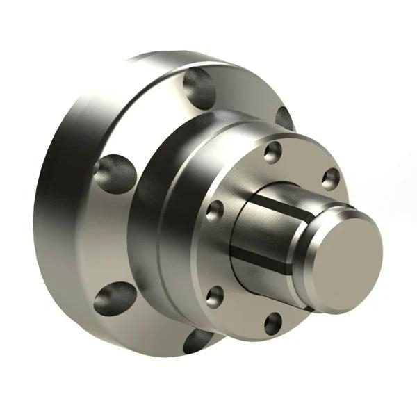
Before implementation, confirm that the bore is suitable as the locating feature for this operation. This review should cover bore size and form, as well as the relationship between the bore and the target OD. Clamping force must transmit cutting torque while limiting workpiece distortion; excessive expansion should not be used as a substitute for a properly designed grip.
During commissioning, check workpiece runout after clamping, the condition of the opposite-end support, and tool clearance across the full travel. If a workpiece size requires additional support, verify that the support does not obstruct the tool path. The part drawing, test-cut results, and inspection records should together determine whether one-setup machining is suitable.
Custom Transfer Rack and Process Validation
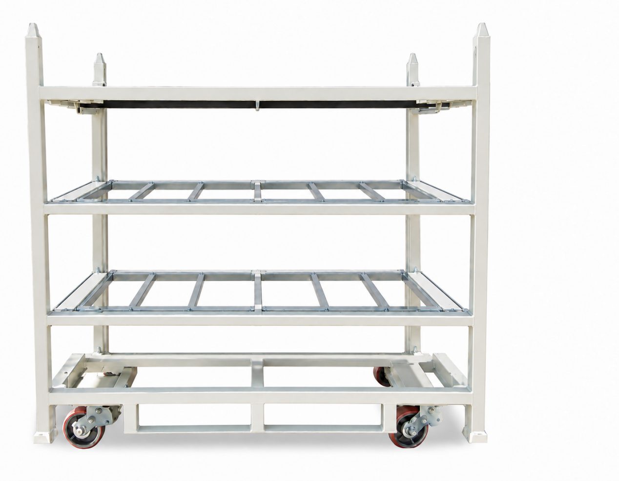
The proposed transfer rack uses plastic V-shaped saddles mounted on its crossmembers. Each rotor rests in its own position, supported by aligned saddles at both ends. Gaps between positions reduce the chance of adjacent parts colliding and help keep machined surfaces away from the metal frame.
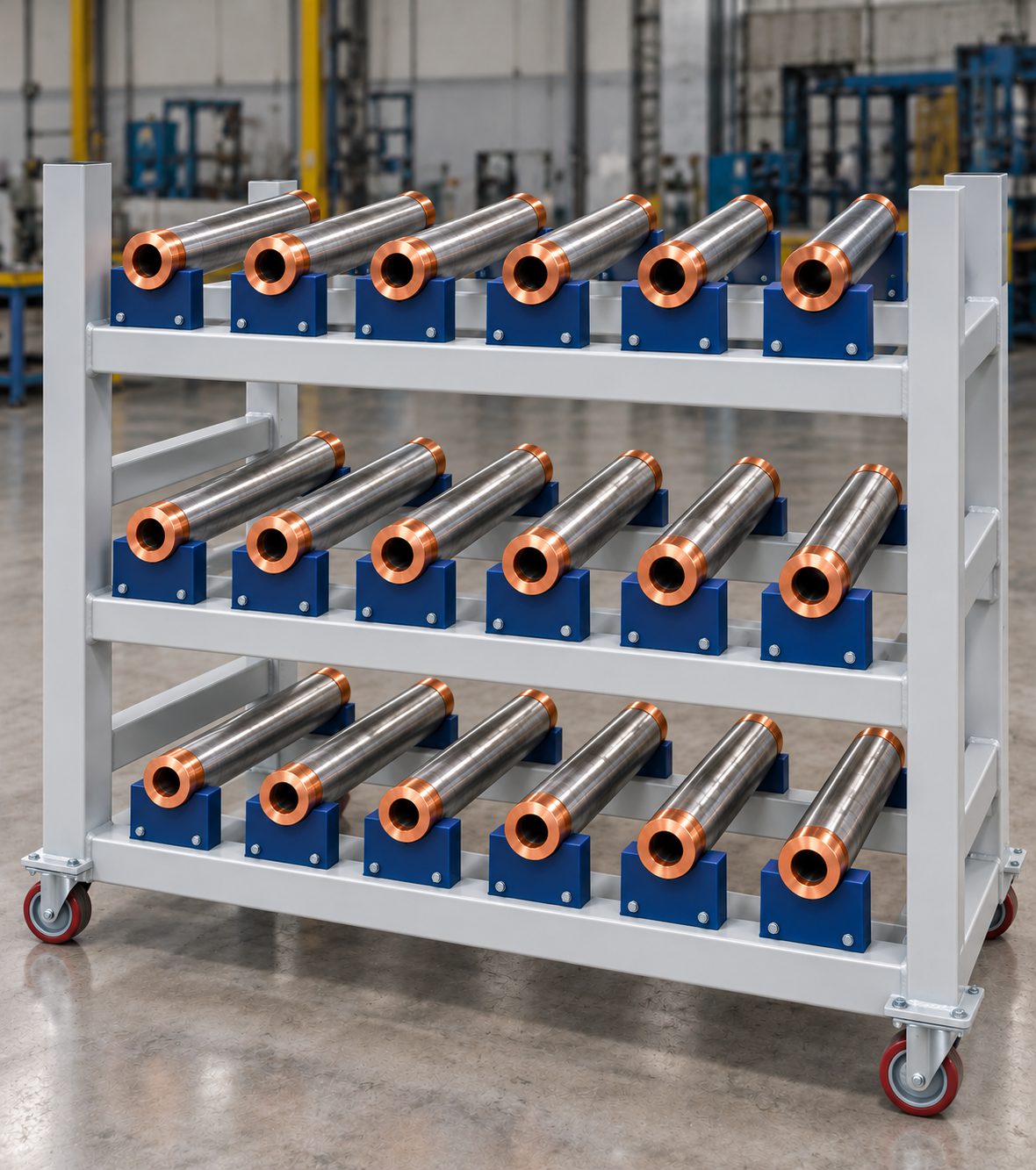
The rack uses reinforced beams and a welded frame. Its top is left clear of crossmembers that could obstruct loading into an upper tier. Saddle depth and height should match the actual rotor diameter so that the part is restrained against rolling while remaining accessible for loading and removal. Support locations, individual part mass, fully loaded capacity, and caster selection must be checked for the actual application. The illustration does not replace fabrication dimensions or a load-capacity check.
Implementation and Acceptance Criteria
The proposed process combines internal-bore locating, open access to the target OD, fewer workpiece reversals, and improved in-process surface protection. The intended benefits are to eliminate the original mid-section transition, reduce repeated alignment steps, and include surface protection in the delivery process.
The available information does not include a post-change production acceptance rate, cycle time, or complete inspection records. No improvement percentage is therefore claimed. Before acceptance, define the inspection characteristic represented by 0.02 mm, then record OD size, applicable geometric accuracy, witness marks at cut transitions, and surface condition. Evaluate production quality and handling damage using a consistent sampling and reporting method.