START YOUR PROJECT
SIPENG CNC logo SIPENG CNCExpert in Advanced Manufacturing
Home / Case Studies / SUS306L Gate Valve Stem Tapered Square Machining

SUS306L Gate Valve Stem Tapered Square Machining

A CNC squaring machine with a dedicated clamping sub-sleeve, spindle taper support and indexable tooling cut the tapered-square cycle on SUS306L gate valve stems from about 3 minutes to 1 minute 20 seconds per piece, with one operator now covering three machines.

SUS306L Gate Valve Stem Tapered Square Machining

For multi-product, small-batch production of SUS306L stainless steel gate valve stems, we machined the tapered square on a CNC squaring machine, supported by a dedicated clamping sub-sleeve, a taper support in the spindle bore and indexable tooling. According to the customer's machining records, the cycle time of this operation dropped from about 3 minutes to 1 minute 20 seconds per piece, and the staffing arrangement moved from one operator per machine to one operator covering three machines.
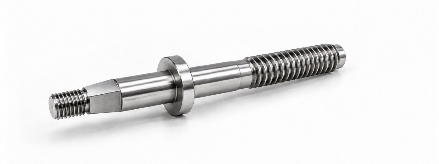
SUS306L gate valve stem with pre-machined ends
The valve stem: both ends and all turned features are pre-machined on CNC lathes. This case covers the tapered-square operation.

Customer Requirements

The customer needed the tapered square machined on stainless steel gate valve stems. The parts cover many varieties, and the batch of each single variety is small, so automatic feeding did not fit the current production plan. With manual loading and unloading kept in place, the customer wanted the per-piece machining time shortened, so that one operator could look after two to three machines.
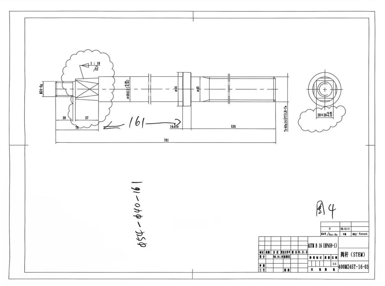
Valve stem engineering drawing
Valve stem drawing (ASTM B16 gate valve). The Ø40 mm cylindrical section between the flange and the tapered square is used for clamping.

Previous Machining Method

The original process produced the tapered square on a machining center with a supplementary rotary axis. That took about 3 minutes per piece for this operation, with one operator responsible for one machine. Both ends of the stem and the other turned features were already pre-machined on CNC lathes; this project focuses on the subsequent tapered-square operation only.

Machine and Workholding Solution

Based on the content of this single operation, we produce the tapered square on a CNC squaring machine. The solution focuses on how the workpiece is held, located axially and tooled, while manual loading and unloading is retained, so the production arrangement fits the actual multi-product, small-batch conditions.

Dedicated Sub-Sleeve Clamping

The stem is clamped on the Ø40 mm cylindrical section between the flange and the tapered square, through a sub-sleeve matched to the workpiece. The sleeve has a central through-bore and four slots connected to the bore, one of which is cut through to the outside diameter to leave room for the sleeve to contract during clamping.
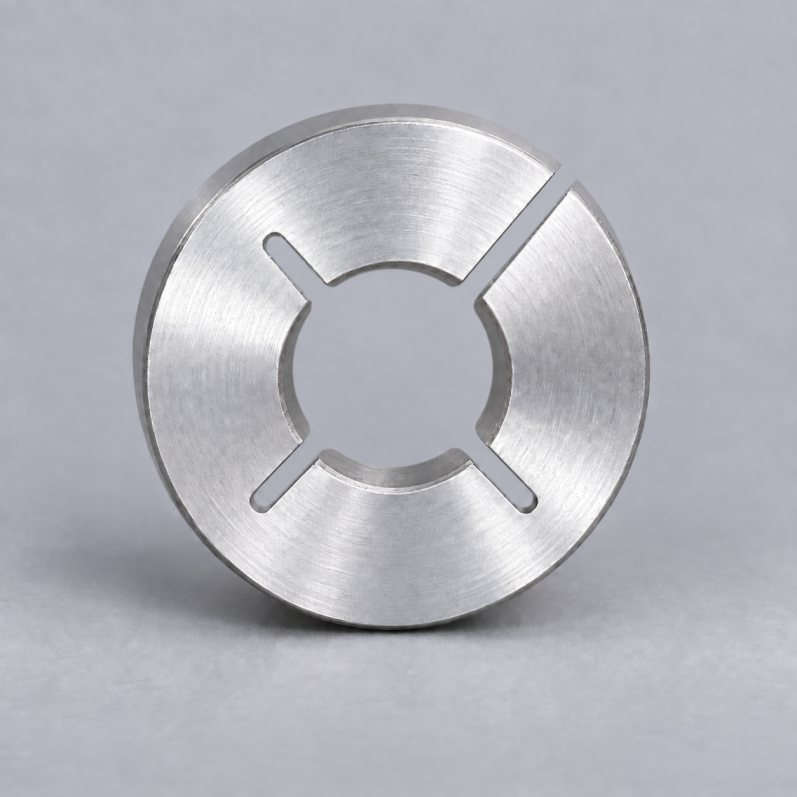
Dedicated clamping sub-sleeve with through-bore and four slots
The dedicated clamping sub-sleeve: central through-bore with four slots, one cut through to the outside diameter for contraction.

Axial Location in the Spindle

The spindle bore carries a taper support used for the axial location of the workpiece. The clamping position and the axial stop work together, so the operator can repeat the machining position at every manual load. The sub-sleeve and the taper support must be matched to the specific part dimensions; they cannot be applied to other specifications by appearance alone.
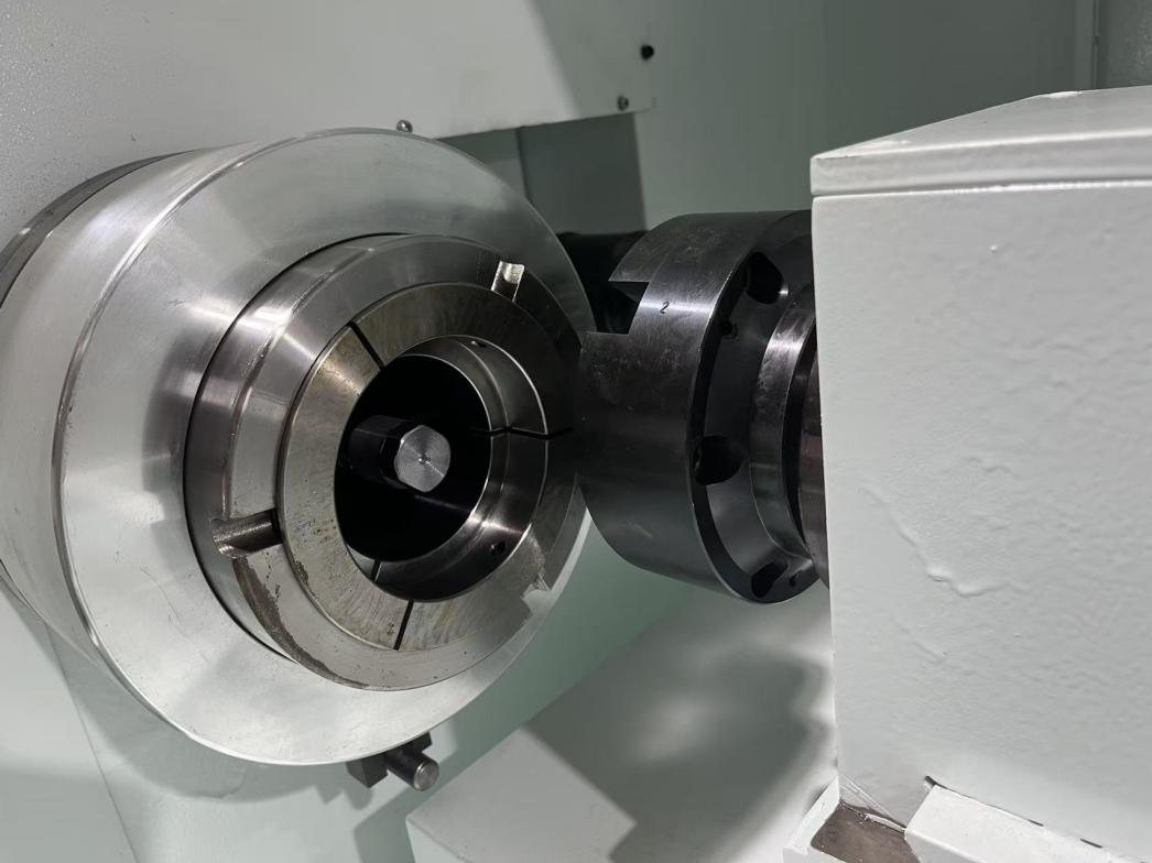
Sub-sleeve mounted in the machine spindle
The sub-sleeve mounted in the spindle, with the taper support behind it.

With both ends of the stem pre-turned, the workpiece is loaded into the sub-sleeve, located against the taper support in the spindle, clamped, and the tapered-square program runs. After the operation the operator removes the workpiece and loads the next one.

Inserts and Tool Holders

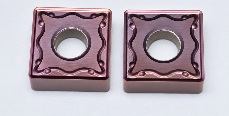
Stainless steel machining is prone to built-up edge, so this project uses indexable inserts with matched holders, configured around the clamping conditions. The inserts shown are square type with 8 usable cutting edges; the holder selected for the job is the configuration circled in red in the photo.
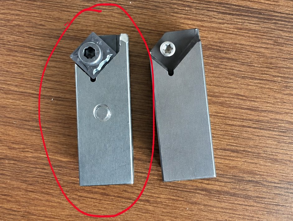
Tool holder configurations tested for the tapered-square operation
Holder configurations for the job: the circled one is the selected configuration.
Square indexable inserts for stainless steel
Square indexable inserts for stainless steel, 8 usable cutting edges per insert.

After one cutting edge wears, the insert is indexed to the next edge in the normal way. Compared with an insert that offers only 4 usable edges, the 8-edge configuration provides more usable corners and helps control insert consumption. Actual tool life and tooling cost per piece still depend on the insert grade, wear condition and cutting parameters.

Machining Results and Use on Site

According to the customer's machining records, the tapered-square operation on similar stems was shortened from about 3 minutes to 1 minute 20 seconds per piece, a saving of about 1 minute 40 seconds (a reduction of roughly 55.6%). These times cover the tapered-square operation only; they do not include the pre-turning of both ends of the stem, nor the total machining time of the complete valve stem.
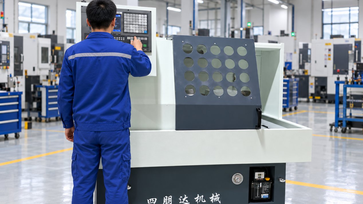
CNC squaring machine in production
The CNC squaring machine in production.

Field records from the customer show the staffing arrangement changed from one operator responsible for one machine to one operator responsible for three machines. Under the machining and loading conditions of this project, the operator can stagger loading and unloading across several machines. Whether other projects can adopt the same arrangement needs to be assessed against cycle time, loading time and the workshop layout.

By configuring the machine, the clamping sub-sleeve, the taper support and the tooling around this specific operation, the project shortened the tapered-square cycle time and improved the staffing arrangement across multiple machines. For similar multi-product, small-batch valve stems, we recommend evaluating the solution from the actual part drawing and the existing process chain.
Other Solutions

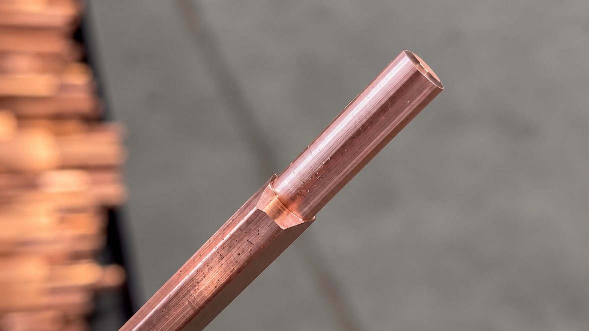
Case Study on the Machining of Copper Rotor Bars for Submersible Pump Motors

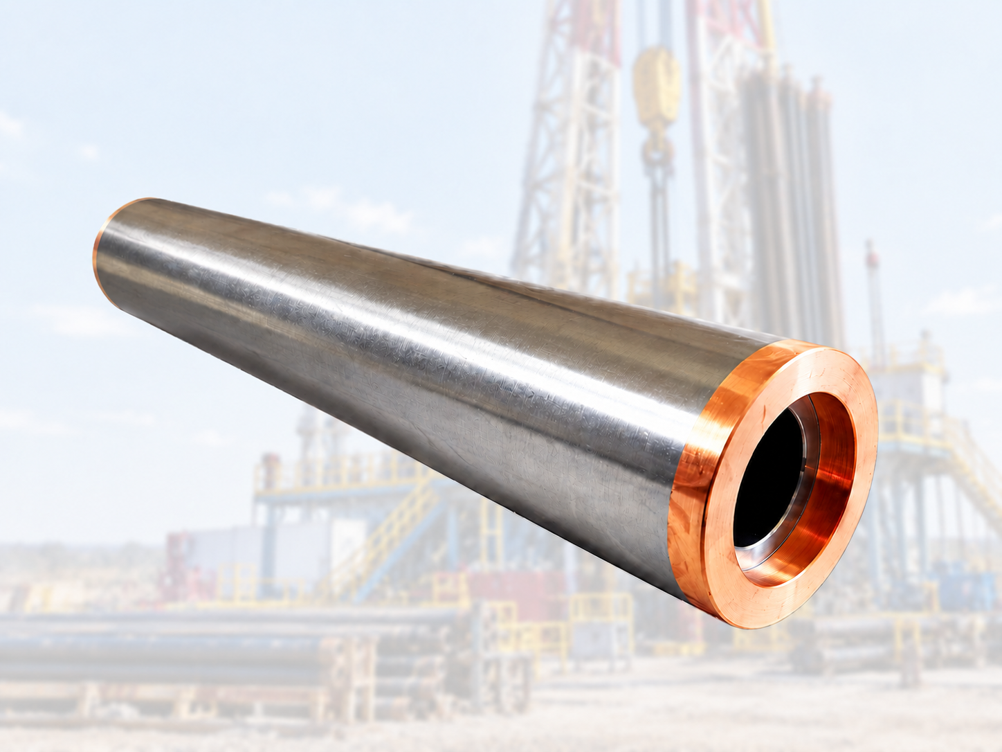
SIPENG CNC developed an automatic CNC turning solution for machining both ends of copper rotor bars used in submersible pump motors. The solution combines dedicated feeding, workholding and internal guidance to improve production output, machining consistency and handling of long copper profiles.

View solution →
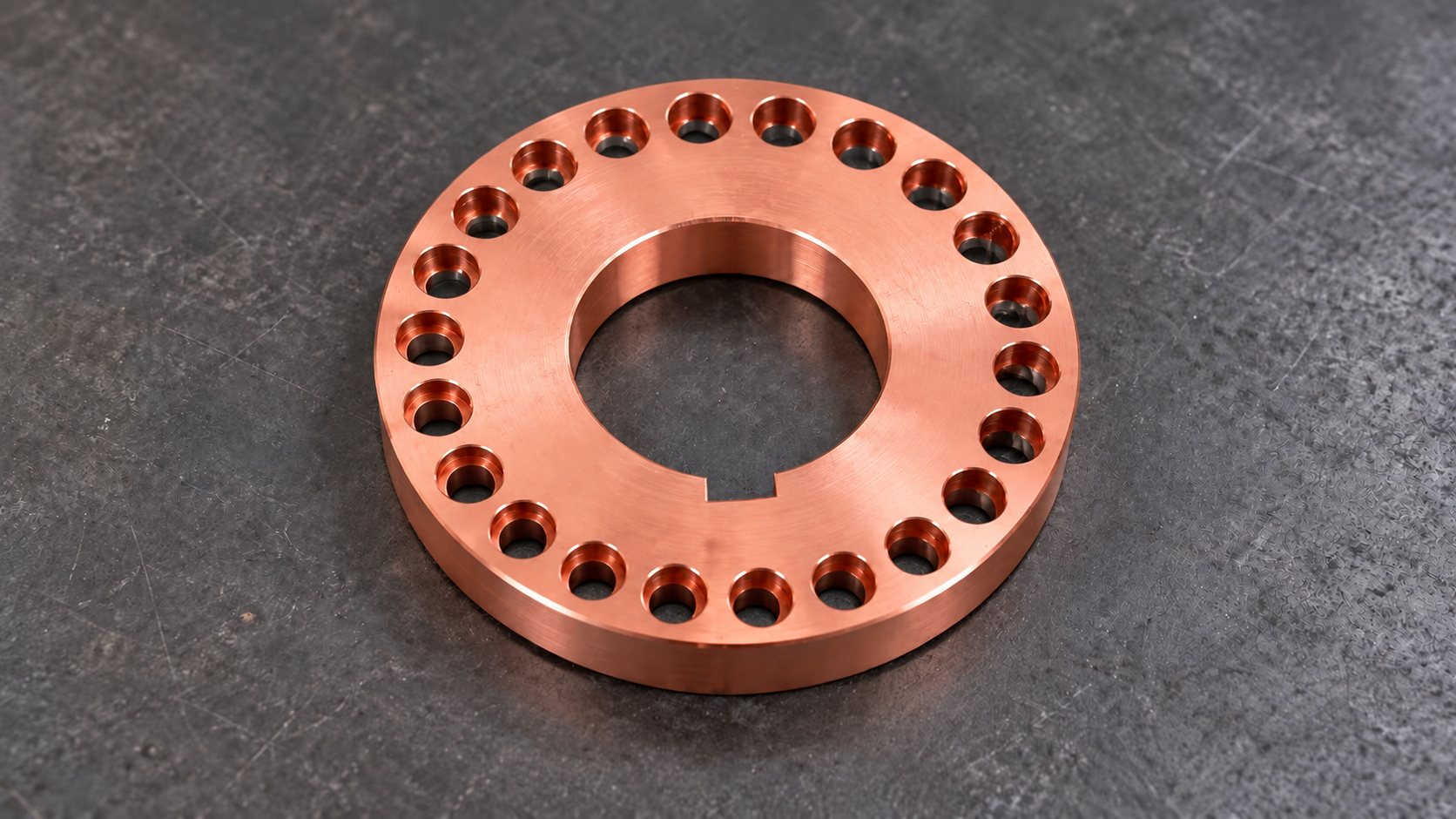
Case Study on the Machining of Copper End Rings for Submersible Pump Motor Rotors

SIPENG CNC developed a drilling and chamfering solution for copper end rings used in submersible pump motor rotors, combining CNC machining, through-spindle coolant and dedicated fixtures to address chip wrapping, manual clamping and repetitive handling.

View solution →
Submersible Pump Motor Rotor Assembly Outer Diameter Machining Case Study

To address issues such as tool switching, repeated alignment, and handling-induced damage during the machining of the outer diameter of submersible pump motor rotor assemblies, this case study reconfigures the machine tool, internal bore clamping method, and workpiece handling process, enabling continuous external turning in a single setup while protecting the machined surfaces.

View solution →
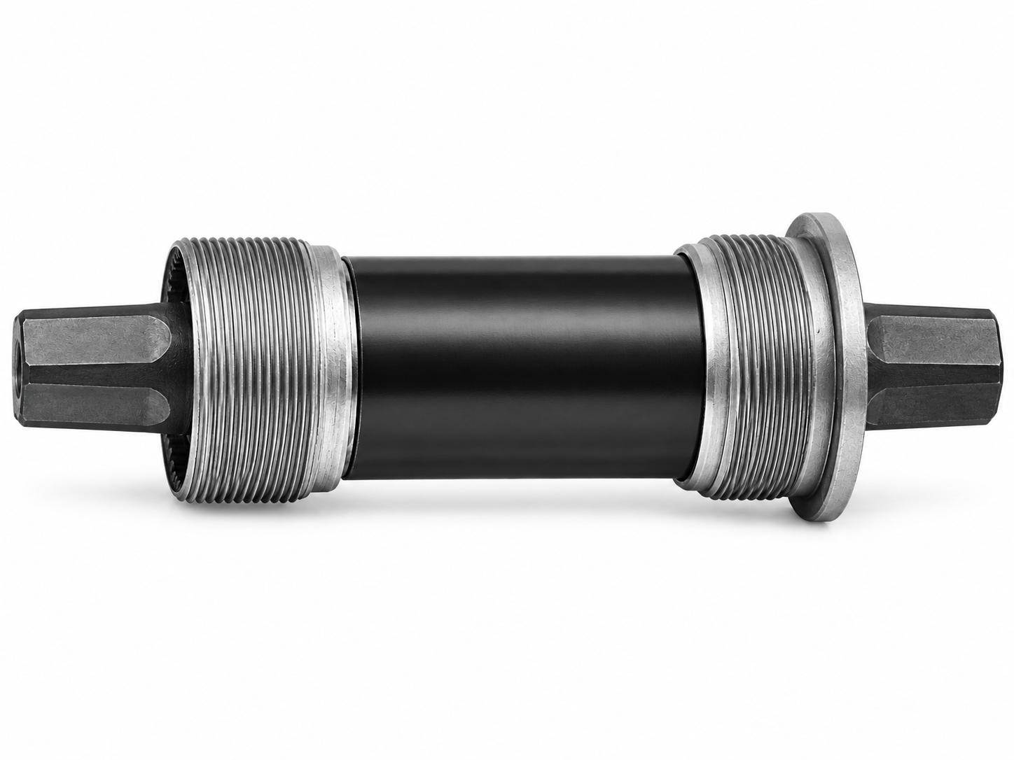
Bicycle Bottom Bracket Spindle End Machining Automation Case Study

A pipe fitting manufacturer replaced scattered manual lathes with a cell of CNC lathes fed by bar feeders. Process planning, tooling packages, part programs and operator training were delivered with the machines, so fitting blanks now move through the cell on a fixed, repeatable route.

View solution →
Prestressed Anchorage Wedge External Taper Machining Automation Case Study

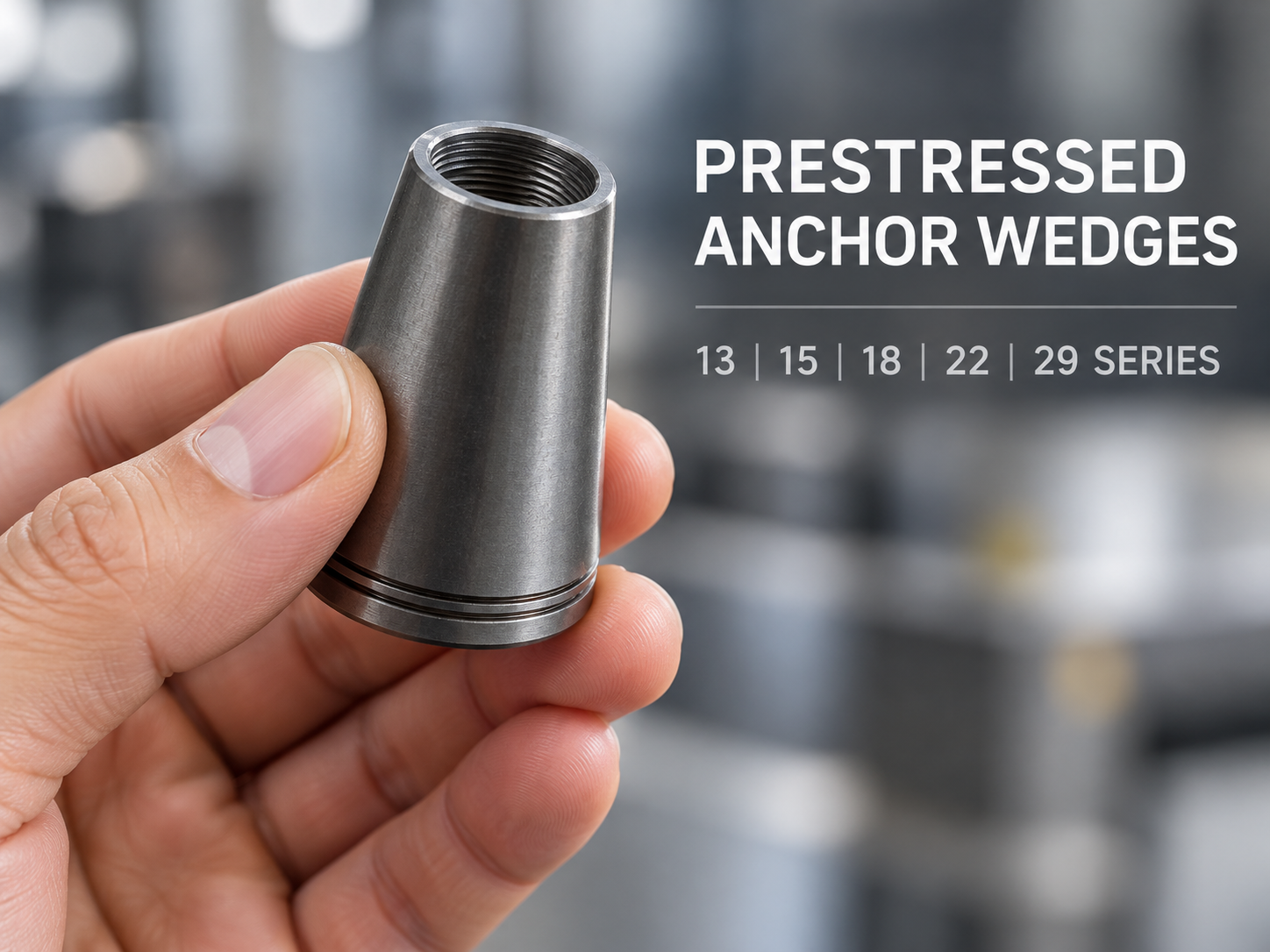
An elevating feeder and dual-channel CNC lathe were added to automate handling for prestressed anchorage wedge turning. The customer reports about 20 seconds per part in the original process and about 14 seconds in the new process; the time scope and production results should be verified on a consistent basis.

View solution →
Integrated Bicycle Disc Brake Rotor Internal Thread Machining

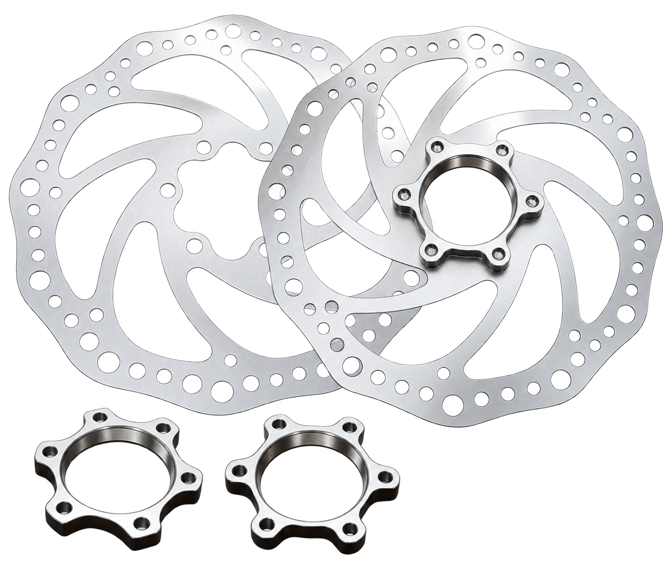
CNC turning case study for a one-piece bicycle disc brake rotor. A dedicated fixture supports the perforated rotor web, approximately 1.8 mm thick, during internal-thread and face machining in one setup. The customer reports an 18-second cycle time; the timing scope and dimensional basis require confirmation.

View solution →
Automated Feeding and Turning for a Shock Absorber Locating Sleeve

An automatic feeding system was integrated with a CNC lathe to machine deep-drawn shock absorber locating sleeves. The original turning process already used one setup but required manual loading and unloading. The customer reports a change from about 10 to 7 seconds per part and one operator tending four to six machines; production conditions should be verified.

View solution →
Automated Turning of Automotive Welding Locating Pins

Precision machining solutions for titanium and aerospace aluminum components with complex geometries and demanding tolerances.

View solution →

Frequently Asked Questions

I can provide drawings, material and blank specifications. Can you recommend the right machine and machining route?
Yes — that is exactly how we start. Send the drawing (PDF, DWG or STEP), material grade, blank dimensions, key tolerances and your target output. Our engineers review the part geometry and process, then recommend a machine model, fixture concept and machining route, together with an estimated cycle time. We reply with a written evaluation and quotation within 24 hours.
Can my part be completed in one setup? Which operations would need other equipment?
It depends on geometry, size and accuracy, so we answer this per part, not in general. After reviewing your drawing we reply in writing: which operations are completed in one clamping, which need a second operation or a different machine, and what the recommended process chain looks like. If a part genuinely needs two setups, we say so instead of promising one-setup results.
Are cutting tools, fixtures, bar feeder and CNC programs included?
They can all be included — the delivery scope is defined line by line in our quotation. A typical turnkey package covers the machine, fixtures designed for your parts, the tooling package, bar feeder integration and CAM programs for your parts, plus a recommended consumables list. If you prefer machine only, or want to keep your existing tooling, the scope is adjusted and every included and excluded item is listed before you sign.
How do you evaluate the machining time for my parts?
We build the process route first, then calculate cycle time from tool paths and cutting data, and cross-check it with CAM simulation. The estimated time per part is stated in the proposal. During trial cutting the actual cycle time is measured; the measured result — not the paper estimate — is the basis for acceptance, so the number you plan production around is a verified one.
Can you run trial cutting with my own material?
Yes, and we recommend it. You send material or blanks; after the machine, fixtures and programs are ready we machine your parts, record cutting parameters, cycle time and tool behaviour, and provide a trial report with measurement results, photos and video. The trial schedule is agreed with you in advance, so you can attend in person or follow it remotely.

HAVE A PART TO PRODUCE?
LET'S BUILD THE RIGHT SOLUTION.

Send us your part drawing, material, tolerance and production requirements. Our team will evaluate the application and recommend the right machine, process and automation configuration.

SEND YOUR PART DRAWING

Share your part and production requirements. Our team will review the application and recommend the next step.

Drawing upload (optional) — supported: PDF, STEP, STP, IGES, DWG, DXF, JPG, PNG, ZIP, DOC, XLS · up to 50MB