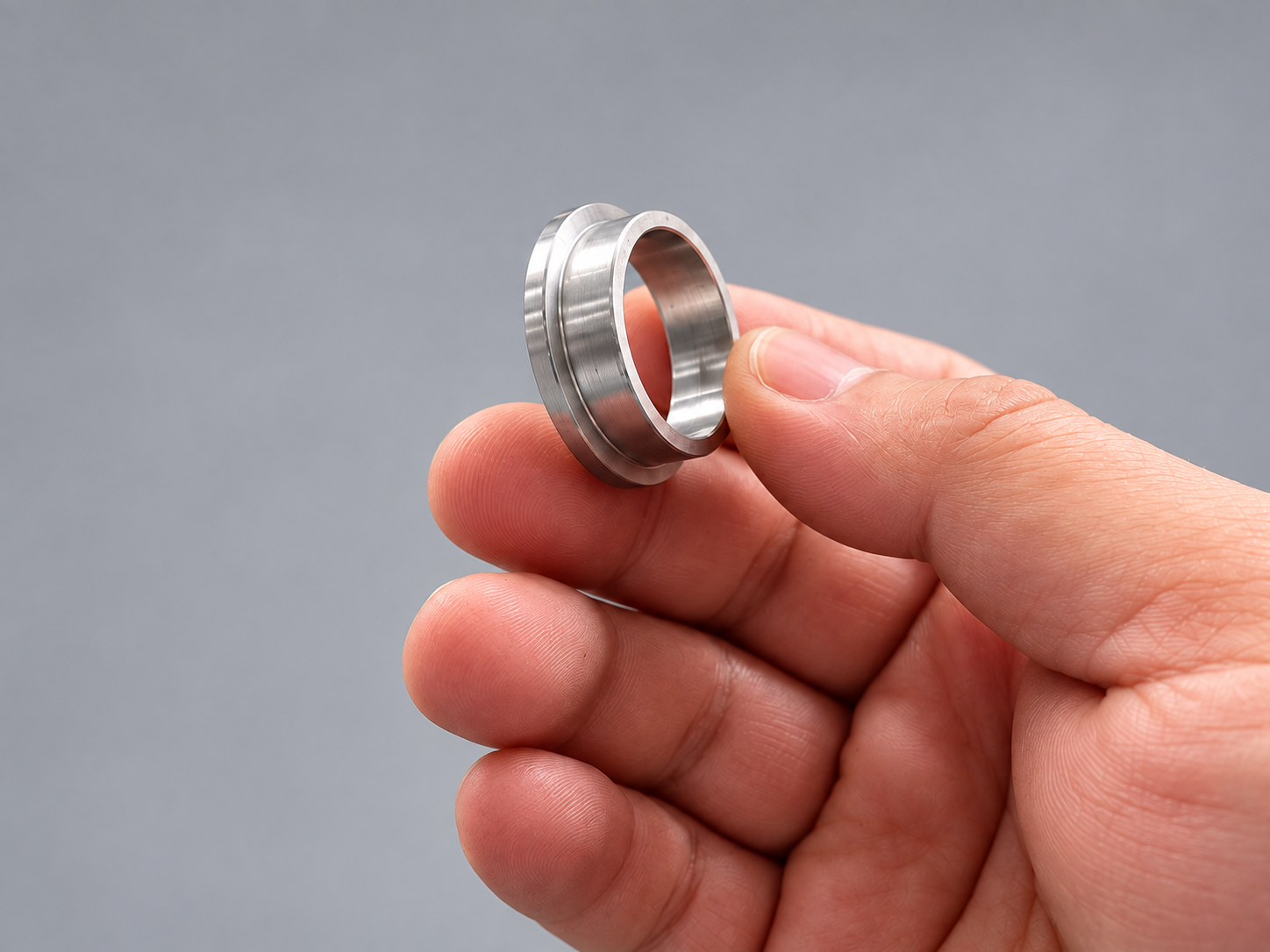
Automated Feeding and Turning for a Shock Absorber Locating Sleeve
SIPENG CNC | Engineering Application Case
This project turns the small-end face and associated internal and external diameters of a deep-drawn shock absorber locating sleeve. The customer’s original process already completed the turning work in one setup, but required an operator to load and unload every part. SIPENG CNC integrated a vibratory bowl feeder with a CNC lathe configured for automatic feeding, then adjusted the tool layout and finished-part discharge during commissioning. The customer reports that the time per part decreased from about 10 seconds to about 7 seconds, and that one operator can tend four to six machines.
Application and Machining Scope
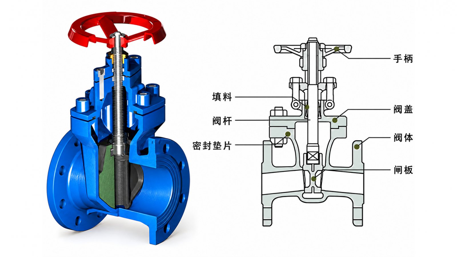
The customer calls the component a locating sleeve used for restraint inside a shock absorber. The customer supplies the deep-drawn blank. This project machines the small-end face and specified internal and external cylindrical surfaces; the drawing defines the exact features and acceptance requirements. The shock absorber cross-section is included to show the application context. It does not establish the sleeve’s exact installed position.
The customer reported poor consistency between the blank’s internal and external diameters, described in the source as “concentricity above 0.2 mm.” The datum and measurement method were not specified. This should be treated as a reported blank variation, not as a finished-part tolerance. The drawing and inspection plan should distinguish axis misalignment, roundness, and rotational runout.
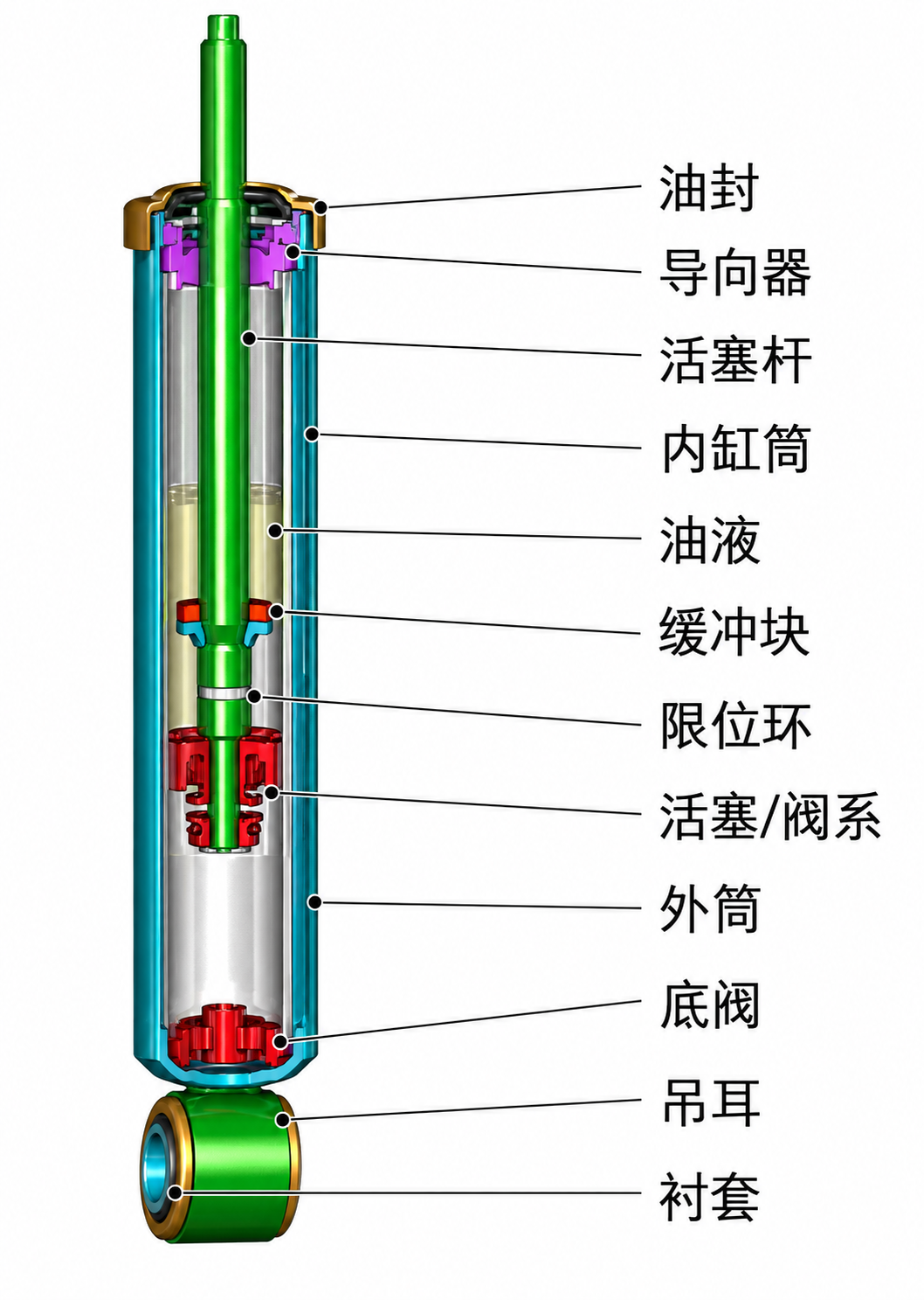
Figure 1. Shock absorber structure
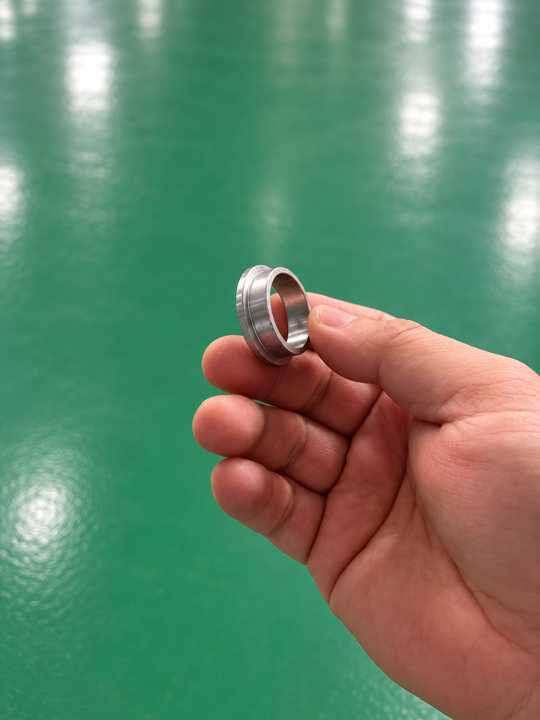
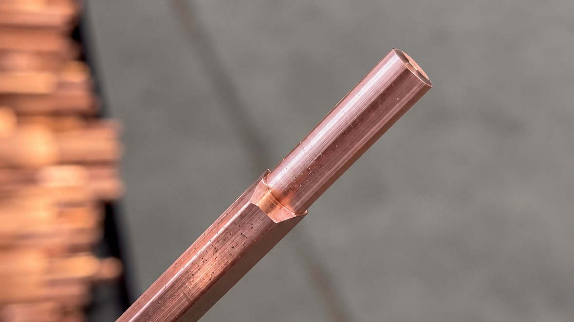
Figure 2. Locating sleeve
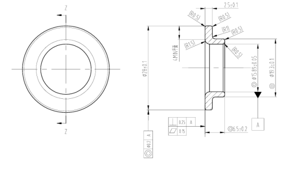
Figure 3. Customer part drawing
Original Process and Automation Need
The customer originally used a conventional CNC lathe and manually loaded and unloaded each part. The turning operation was completed in one setup, with a customer-reported time of about 10 seconds per part. Because the component has a relatively low unit value, the customer considered it costly for one operator to tend one machine and sought automatic feeding and machining.
The improvement objective was to reduce one-by-one manual handling and coordinate feeding, clamping, cutting, and discharge for continuous operation. One-setup machining was already part of the original process; the proposed value lies in automated handling and the potential to increase the number of machines tended by one operator.
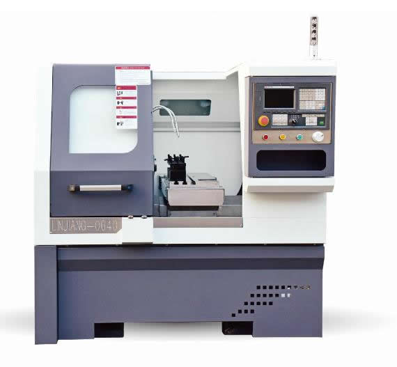
Figure 4. CNC lathe used in the original process
Vibratory Feeder and CNC Lathe Integration
SIPENG CNC configured a CNC lathe with an automatic feeding mechanism and a vibratory bowl feeder. An operator replenishes a batch of blanks. The feeder orients the parts, transfers them through a linear track and loading mechanism into the collet, and the machine discharges finished parts to a collection bin. The exact sequence depends on the installed mechanism and control program.
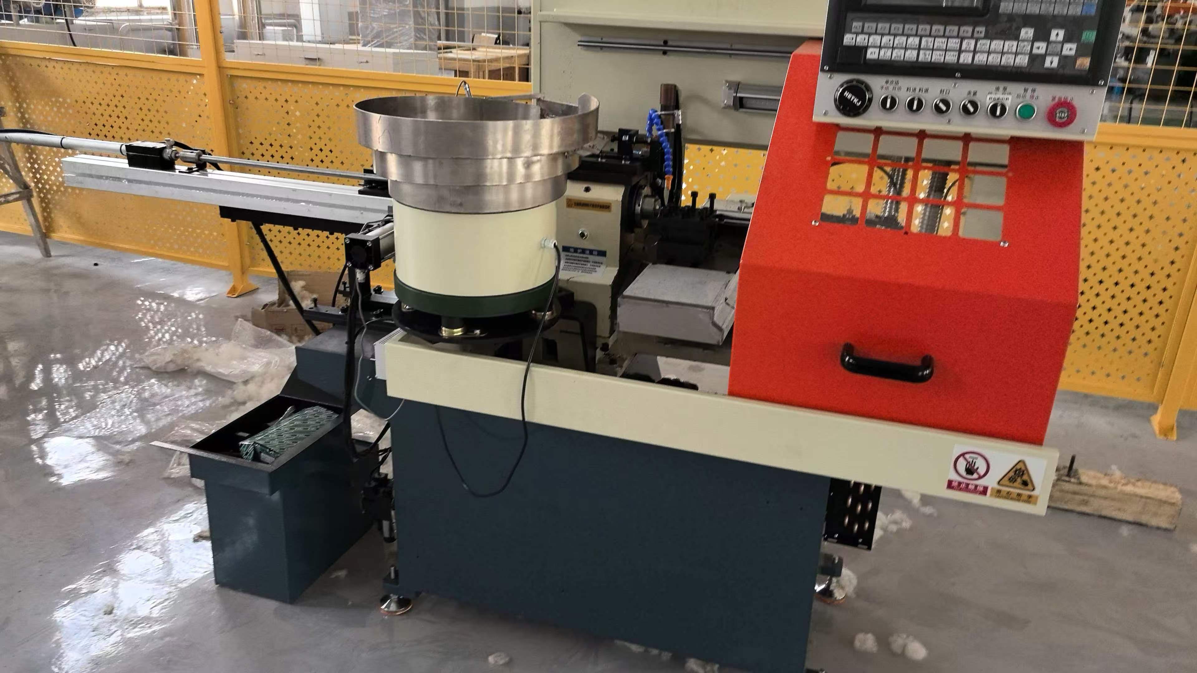
Figure 5. Vibratory bowl feeder integrated with an automatic CNC lathe
Short flanged sleeves can enter the track in the wrong orientation, overlap, or jam. The feed track and final loading mechanism must match the blank’s dimensions and orientation. Commissioning should confirm single-part separation and the conditions for feed completion, clamping, and withdrawal. The source does not specify detection or interlock functions, so none are claimed here.
Commissioning Focus and On-Site Improvements
Part Orientation and Clamping Alignment
The customer reported that a part entering the collet in the wrong orientation or with excessive radial runout could jam near the spindle and affect output and quality. Troubleshooting should check blank eccentricity, feed orientation, loader alignment, and collet location separately. A feeding jam should not automatically be attributed to poor “concentricity.”
The feeder should present the part axis in line with the collet entry and should not force a misaligned part into the spindle. During clamping, confirm that the part seats against its axial stop and has sufficient effective clamping length. Trial cuts with representative blanks should verify the locating and clamping conditions. For deep-drawn sleeves, inspect the part after unclamping to check for distortion that could affect acceptance.
Tool Layout and Finished-Part Discharge
During early commissioning, the two tools were mounted on separate tool stations, which required a longer auxiliary traverse. Finished parts also accumulated in a small receiving trough on the middle slide. SIPENG CNC moved both tools to the same tool station and adjusted their approach and retract positions to reduce unnecessary movement. An air-blast device was added to help direct finished parts into the collection bin.
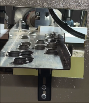
Figure 6. Tool station area inside the machine
The customer reported that finished parts no longer accumulated in the original trough after the adjustment. The air direction, timing, and discharge path must work together to avoid part rebound or chips entering the locating surface. Increasing air pressure alone is not a reliable solution. After consolidating the tools, check for interference among the tools, collet, and feeding mechanism.
Tooling and Continuous-Production Checks
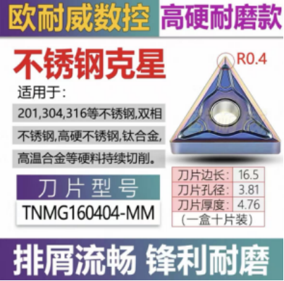
Figure 7. TNMG160404 MM insert
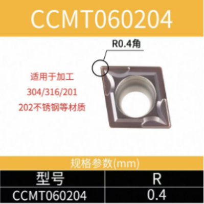
Figure 8. CCMT060204 insert
The source includes product images of these two insert types but does not identify the final grades, coatings, operation assignments, or workpiece material. Product descriptions such as “suitable for stainless steel” do not establish the part material or prove tool life. The production tool plan must be matched to the material, stock allowance, and available cutting space.
Continuous Production and Quality Inspection
Automation acceptance should record feed jams, clamping misalignment, discharge accumulation, and abnormal stops. Stability should be checked with blanks from different lots. A successful single-part trial or a short jam-free run does not establish reliable operation over a full shift.
After unclamping, inspect the small-end internal and external diameters, the end face, and any geometric relationships specified on the drawing. Use the appropriate methods for dimensional measurement and rotational runout; visual observation alone is not a substitute for inspection. The source provides no confirmed material, tolerance results, pass rate, or tool-life data, so none are stated here.
Information to Confirm Before Publication
Confirm the workpiece material and accepted blank range, the measurement basis for the reported “above 0.2 mm” variation, the final machine model and collet locating method, the actual production tooling, and the measurement scope for the reported 10-second and 7-second times. Also verify the operating conditions and quality records behind the reported one-operator-to-four-to-six-machines arrangement.
Machining Time and Staffing
The customer reports about 10 seconds per part for the original process and about 7 seconds for the new process. If both figures cover the same sequence of actions, the time per part is approximately 30% shorter and the theoretical continuous output rate is approximately 42.9% higher. The source does not include a complete timing record. Before publication, confirm whether the measurements include loading, clamping, cutting, and finished-part discharge.
Measure | Original Process | Automated Process |
Loading and unloading | Manual, one part at a time | Vibratory bowl feeding with automatic loading and unloading |
Setups for the turning operation | One | One |
Customer-reported time per part | About 10 s | About 7 s |
Machines tended per operator | Source describes one operator per machine | Customer reports one operator tending four to six machines |
Theoretical output per hour | 360 parts per machine | About 514 parts per machine |
The theoretical output figures in the table assume uninterrupted operation with no downtime or rejected parts; they are not guaranteed good-part shift output. The customer’s report that one operator can tend four to six machines depends on replenishment frequency, tool life, inspection, chip clearing, and exception handling. It does not by itself establish an equivalent reduction in labor cost.
Project Conclusion
The project added automatic feeding to one-setup turning. Commissioning consolidated the tools and added air-assisted discharge. The customer reports about 7 seconds per part and one operator tending four to six machines; confirm with continuous-run and good-part records.