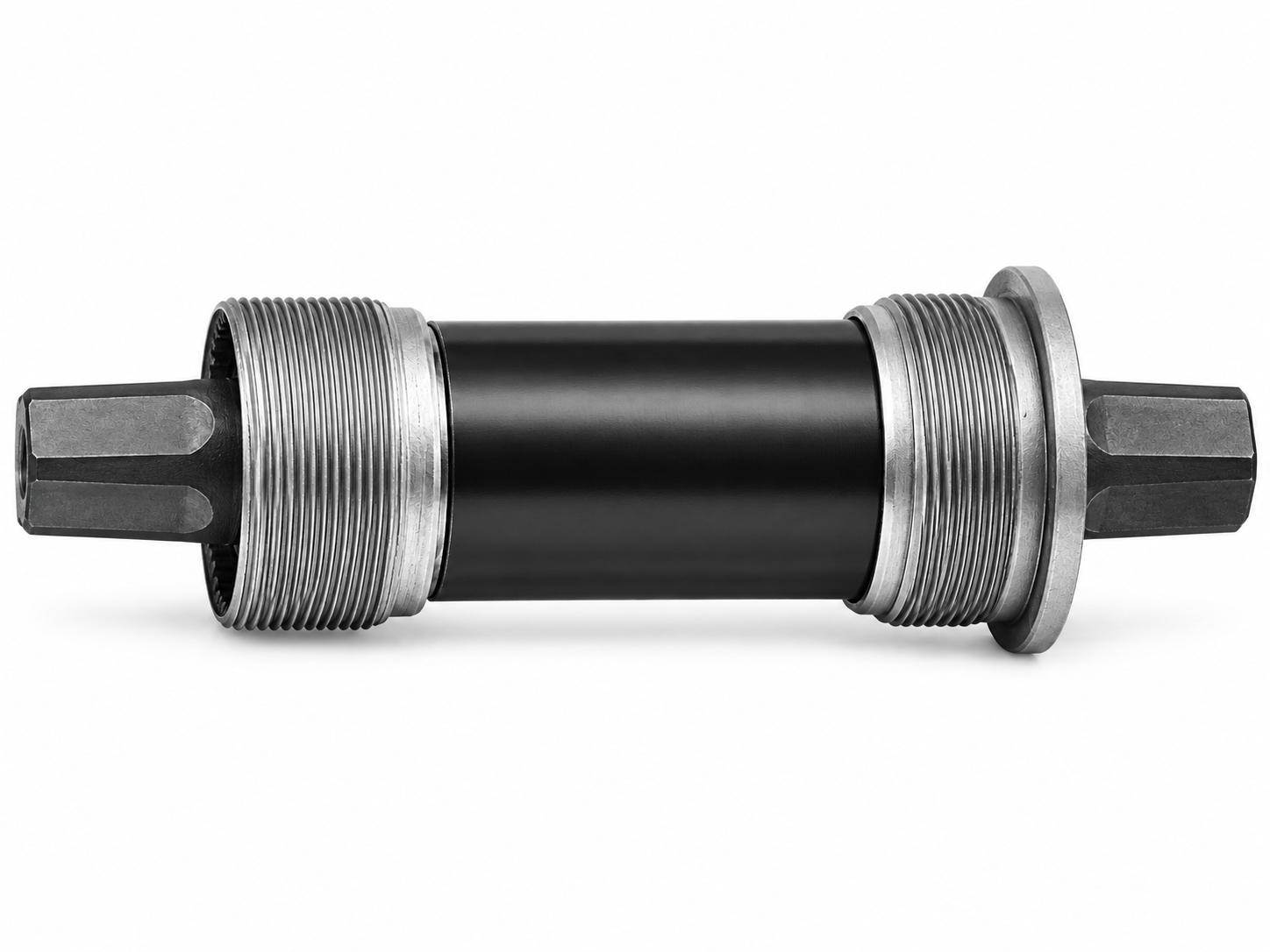
Bicycle Bottom Bracket Spindle End Machining Automation Case Study
SIPENG CNC | Engineering Application Case
This project reorganized machining at both ends of a bicycle bottom bracket spindle. The customer moved from using two CNC lathes, one for each end, to a dedicated multi-station machine with automatic loading, part transfer and unloading. The process was designed to reduce handling between operations and improve control of the relationship between the two end-hole axes. That relationship still requires measurement and validation on the actual machine.
Part and Machining Requirements
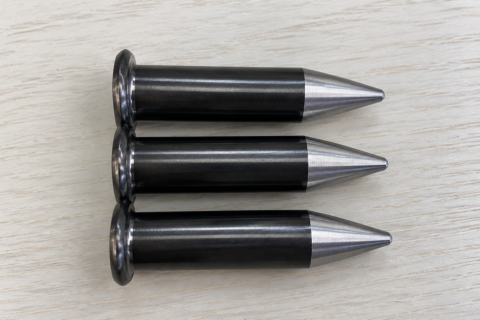
The workpiece is a bicycle bottom bracket spindle. The customer typically uses ML45 steel, with 42CrMo used on some higher-grade products. The stock condition and hardness should be confirmed separately for each material before cutting data and tool life are established; one parameter set should not be assumed to suit both.
At each end, the operations are face machining, center drilling, drilling with chamfering, and tapping an M6 internal thread. The stated requirements are a 5.3 mm drilled hole to a depth of 20 mm and a 15 mm thread depth. The thread must pass the specified GO and NO-GO gauges. The drawing should define whether the hole depth refers to the cylindrical portion and whether thread depth means effective full-thread depth. The pilot-hole size should be confirmed against the thread pitch, tap type and workpiece material.
The customer specifies a concentricity limit of 0.1 mm between the two ends. Before acceptance, the drawing should identify the measured features, datum axis and inspection method. The requirement should distinguish the relationship between the two hole axes from runout relative to the outside diameter.
Station Sequence and Control Points
Station | Operation | Primary control point |
1 | Face both ends | Facing allowance and axial position |
2 | Center drill both ends | Center-hole location and guidance for subsequent drilling |
3 | Drill and chamfer both ends | Hole diameter, depth, chamfer and chip evacuation |
4 | Tap M6 threads at both ends | Effective thread depth and GO/NO-GO gauge results |
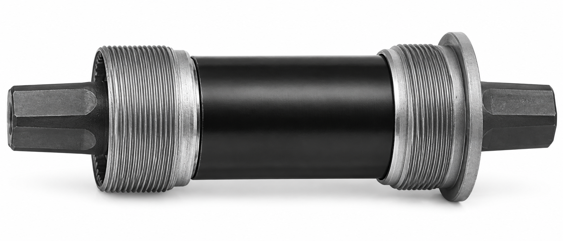
Figure 1. Bicycle bottom bracket assembly
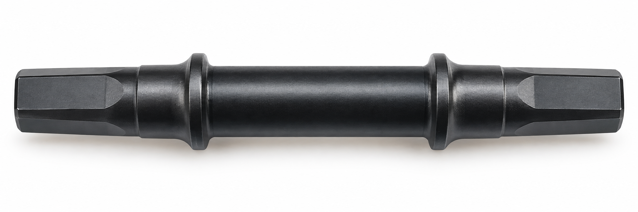
Figure 2. Bicycle bottom bracket spindle processed in this case
Original Process and Engineering Focus
In the original process, one operator tended two CNC lathes, with each machine processing one end of the part. The customer reported an approximate 85-second time to complete a part and an output of about 320 pieces per eight-hour shift. These figures describe different measures—cycle time and shift output—and should be compared only after their measurement boundaries are aligned.
Two separate setups can affect the alignment of the holes at opposite ends. The auxiliary sleeve, its internal-to-external concentricity, the fit between its two halves, the workpiece position after clamping, and the condition of the machine and tools should all be checked. Re-clamping is one possible source of error; it should not be treated as the sole cause of an out-of-tolerance result without inspection evidence.
A two-piece auxiliary sleeve surrounds the center cylindrical section and is then clamped by a spring collet. The sleeve needs enough allowance for clamping so that its split faces do not meet before the workpiece is held securely. Axial location, clamping length and tool access also need to be confirmed. Reducing overhang can improve setup rigidity, but runout checks and trial cuts are still needed to verify the result.
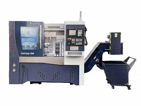
Figure 3. CNC lathe used in the original process
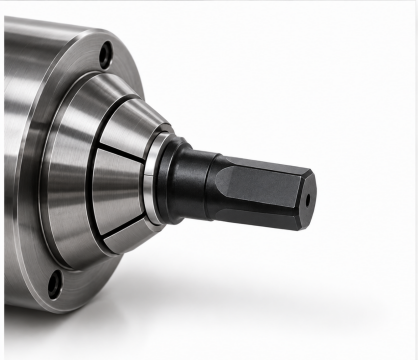
Figure 4. Spring collet and auxiliary sleeve setup
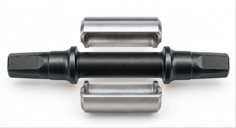
Figure 5. Two-piece auxiliary sleeve
The original cycle also included loading and unloading, transfer between machines, and tool movements. Tapping time should be assessed using actual machine motions and cutting conditions, including spindle speed, synchronized feed, reverse withdrawal, chip evacuation and tap condition.
Dedicated Multi-Station Automation
The proposed machine uses a raw-part magazine at the front. A handling system picks up and transfers each workpiece through the machining stations, then sends finished parts to a rear collection magazine. Four driven units are arranged on each side of the machine to perform the corresponding operations at both ends. The exact coordination between the two sides and the sequence of station actions must be confirmed against the control program and commissioning records.
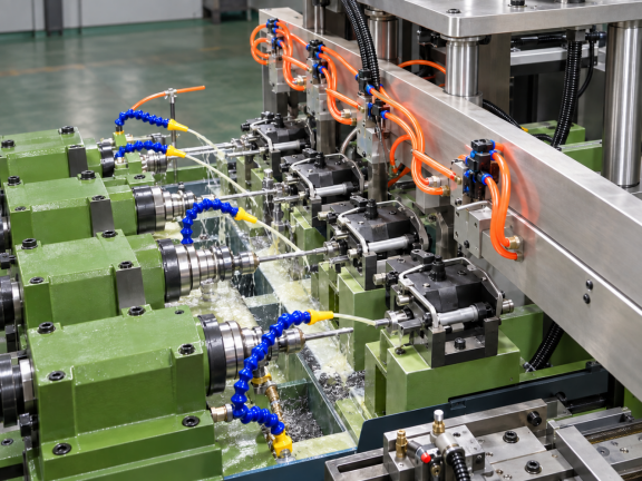
Figure 6. Machining area of the dedicated two-sided multi-station machine
A multi-station layout can reduce tool-change and manual-transfer waiting within the machine. The main quality controls are alignment of the driven units, workpiece location and repeatability after transfer. If the part is re-clamped between stations, positioning error remains possible; automation does not replace validation of the locating accuracy.
Each station should use a clearly defined, consistent locating datum. During commissioning, the relationship between both sets of driven units and the workpiece datum should be checked. Measure the actual axis deviation between the two end holes and confirm stability during cold-start, warm-running and continuous-production conditions before setting production parameters.
Combined Tooling and Production Controls
The drilling station uses a custom drill-and-chamfer combination tool to produce the pilot hole and the entry chamfer in one feed, eliminating a separate chamfering motion. Its step position, cutting diameters and effective length must match the specified hole depth and chamfer. Tool-to-fixture clearance should also be checked.
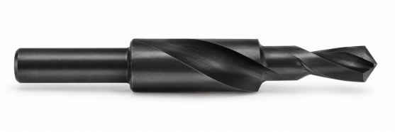
Figure 7. Custom drill-and-chamfer combination tool
Tool Length and Replacement Reference
After a drill is reground or a tap is replaced, confirm tool length and machining depth from a consistent measurement reference. Regrinding the combination drill can change the axial relationship between its drill point and chamfering edge. Checking only the overall length offset may therefore leave the chamfer incorrect. Establish separate replacement or regrinding intervals for each material and hardness.
Tool Breakage Detection and Response
The customer encountered drill breakage during commissioning and also needs to address tap breakage. The production control plan should include checks for both tools and define how the machine stops, raises an alarm, isolates affected workpieces and triggers reinspection after an abnormal event. The detection method should be selected for the actual tools and machine configuration; part count alone cannot confirm tool condition.
Continuous-production records are needed to establish tool life. Record the material, tool ID, accumulated part count, number of regrinds and any abnormal events. Set preventive replacement intervals with an appropriate margin, then adjust them using hole diameter, chamfer, thread depth and gauge results. Automatic tool-life management and in-process broken-tool detection should be treated as specific machine functions to be confirmed and validated.
Blind-Hole Tapping and Chip Clearance
The 5 mm difference between the 20 mm drilled depth and 15 mm thread depth is not entirely available as a safety allowance. Confirm the drill-point length, the tap lead, bottom clearance and chip space to ensure the required full thread depth is achievable. Cutting data and tap selection should be validated by trial cuts for the material, hole type and coolant or chip-evacuation conditions.
Cycle Time and Output Basis
The customer reports an approximately 20-second part output interval with the new process. For a multi-station machine, record the interval between successive finished parts during stable continuous production separately from the total time a single part spends moving from loading to unloading. These measures are not interchangeable.
At a 20-second output interval, uninterrupted production with no rejected parts would yield 1,440 pieces in eight hours. The customer-reported shift output for the new process matches this theoretical figure. Before publishing it as achieved production, verify whether the count accounts for replenishment, tool changes, faults, inspection and scrap. Compared with 85 seconds, 20 seconds is approximately 76.5% shorter; the theoretical output rate is about 4.25 times higher. Both comparisons require consistent measurement definitions.
The reported staffing arrangement—one operator tending six machines—describes a possible labor configuration. Its suitability depends on replenishment, inspection, tool-change and exception-handling workload. Record operator activity while the machines run concurrently before assessing sustained production capacity and labor cost per part.
Measure | Original process | New process |
Staffing reported by customer | 1 operator tending 2 CNC lathes | 1 operator tending 6 dedicated machines |
Time measure | About 85 s to complete a part | About 20 s between finished parts |
Customer-reported output per 8-hour shift | About 320 parts | About 1,440 parts per machine |
Theoretical output at the stated time | About 339 parts at 85 s each | 1,440 parts at 20 s each |
Quality Validation and Project Value
Acceptance inspection should cover the relationship between the two end-hole axes, pilot-hole diameter and depth, chamfer, effective M6 thread depth, and GO/NO-GO gauge results. The sampling plan should include the first article, parts produced after a tool change, and parts sampled during continuous production. Keep records that can be reconciled with shift output, downtime and tool replacement.
The project combines dedicated machining stations with automatic part transfer for a repeat-production component. The customer reports a wider operator-to-machine coverage and a shorter finished-part interval. Any final claims about output improvement, process capability or cost savings should be supported by continuous-run records using the same material, inspection criteria and production-accounting basis.