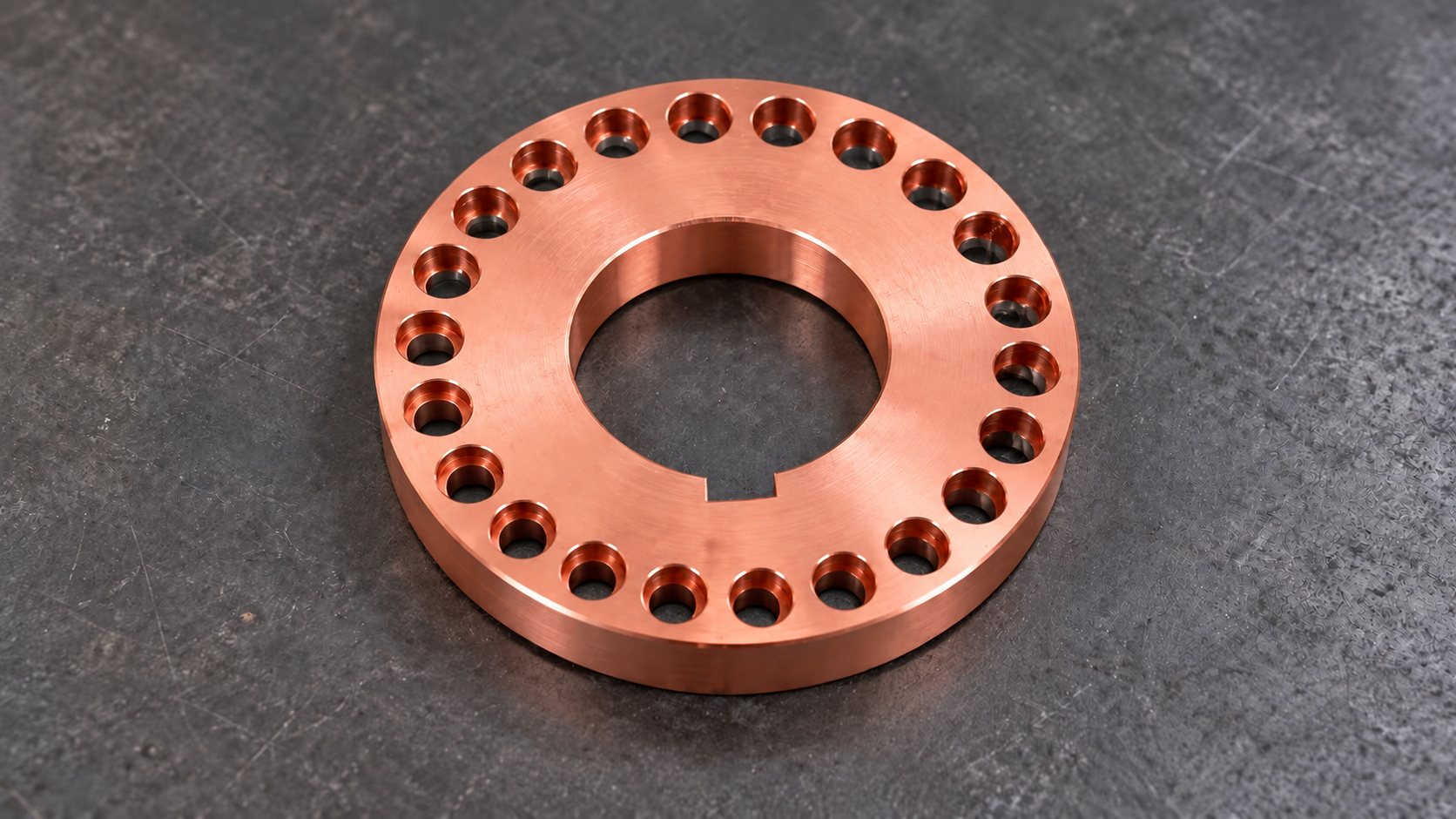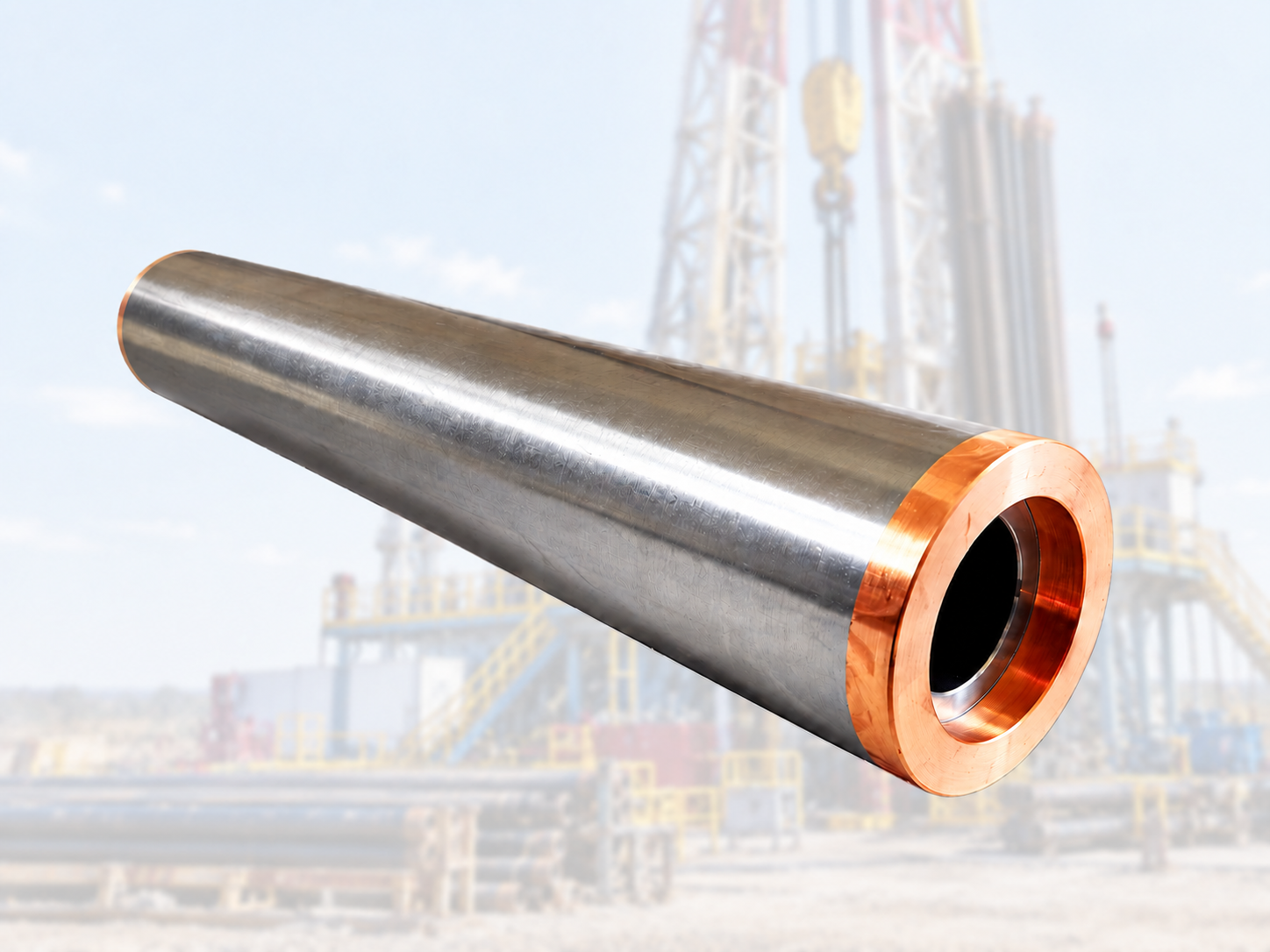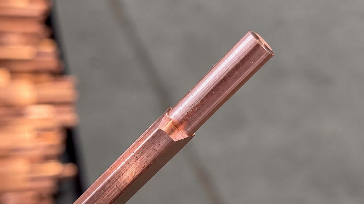
Copper rotor bars are the electrical conductors of submersible pump motor rotors. The motor works downhole in the oil well, submerged in production fluid, where the rotor bars carry the full motor current and any inconsistency in the bars is amplified into vibration, noise and premature bearing wear. The bars are long, soft and easily deformed, which makes their end machining a dedicated production problem rather than a general turning job.
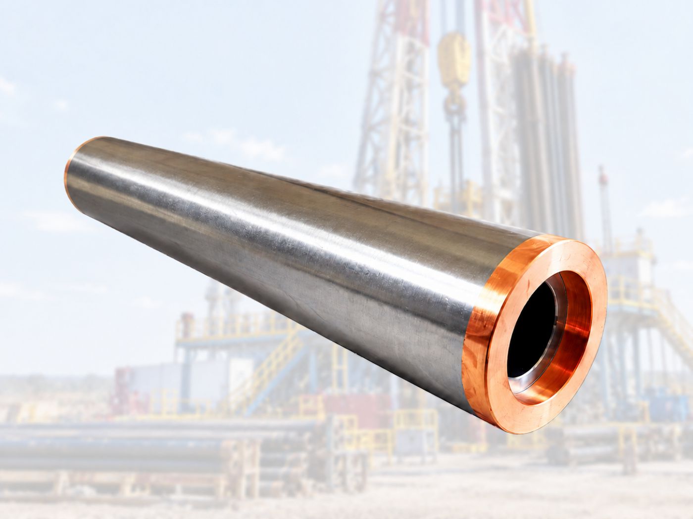
Project Overview
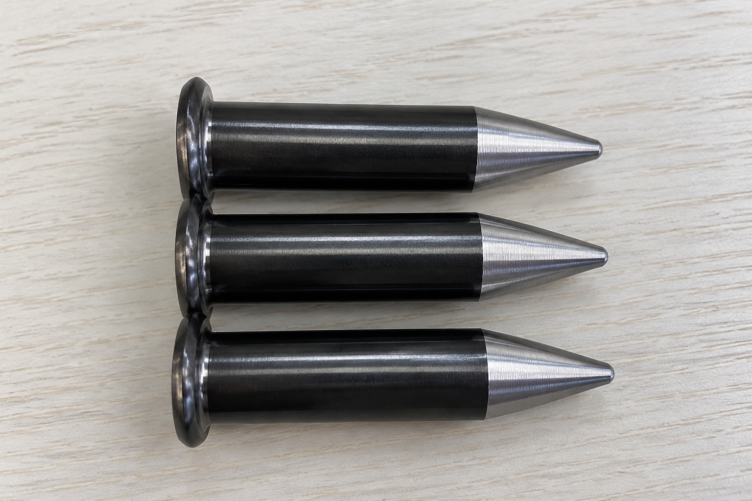
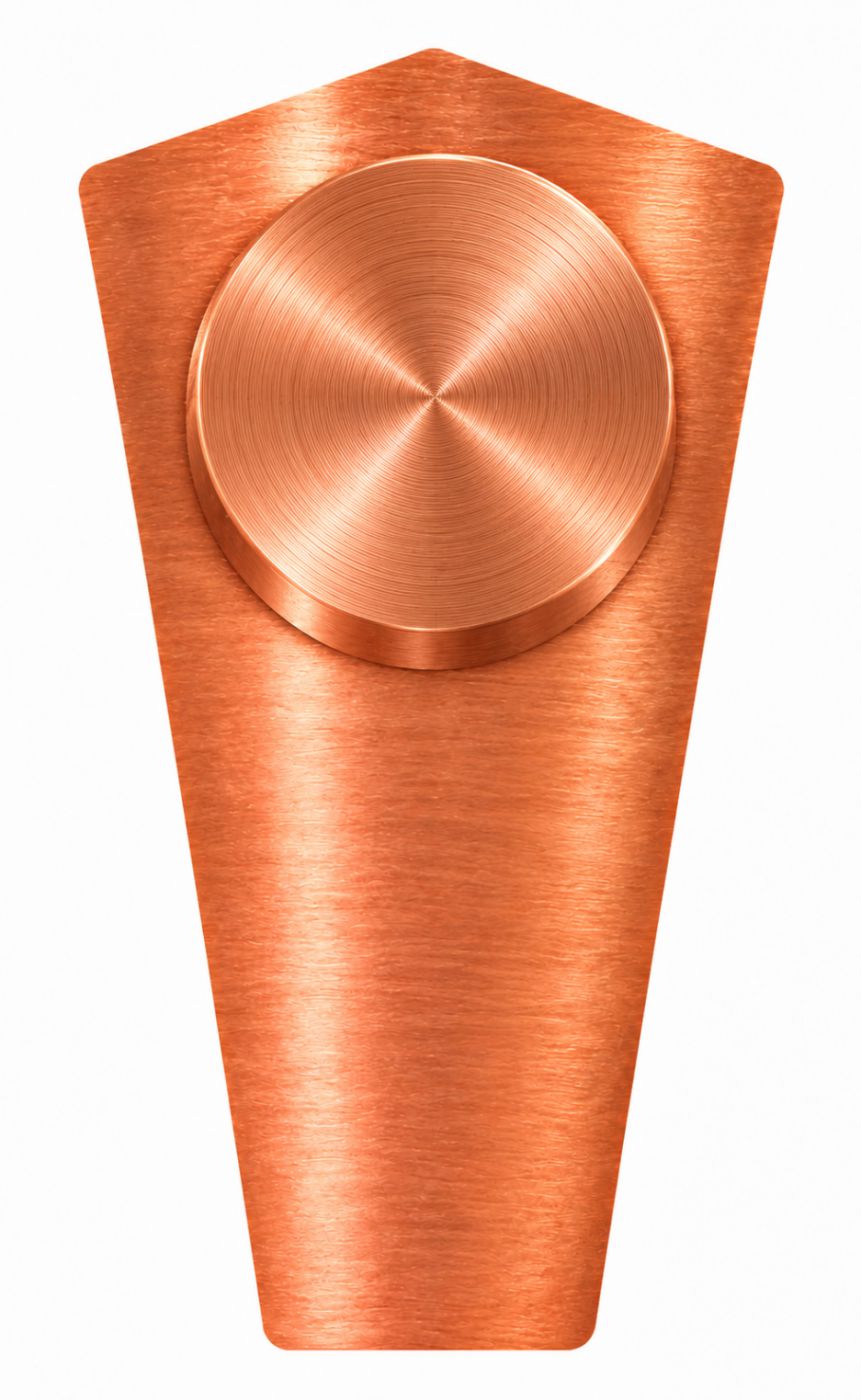
The customer machines shaped (profiled) copper rotor bars for submersible pump motor rotors, drawn from T1 and T2 copper. Both ends of every bar must be turned into a cylindrical seat of Ø5.23 mm × 16.5 mm, and the bars delivered for this project range from 352 mm to 612 mm in length.
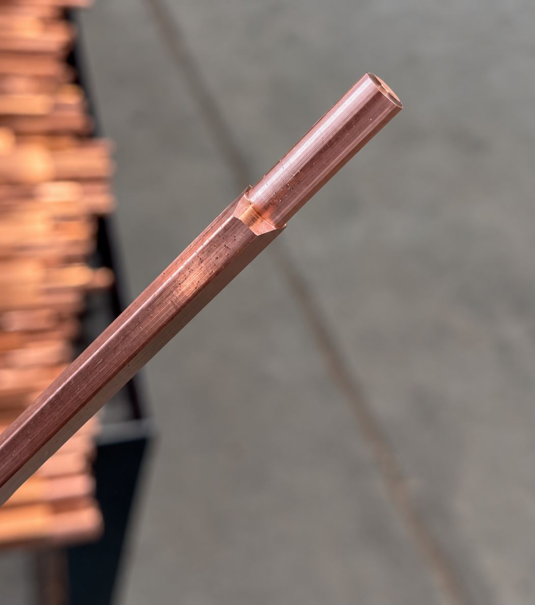
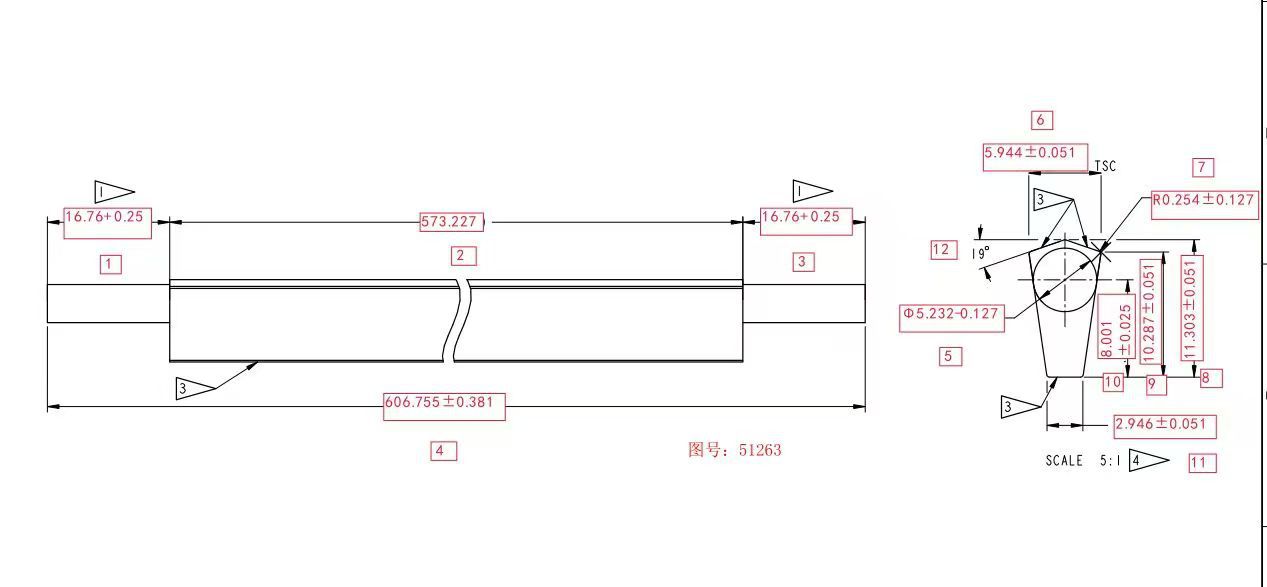
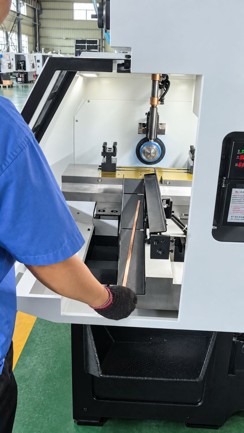
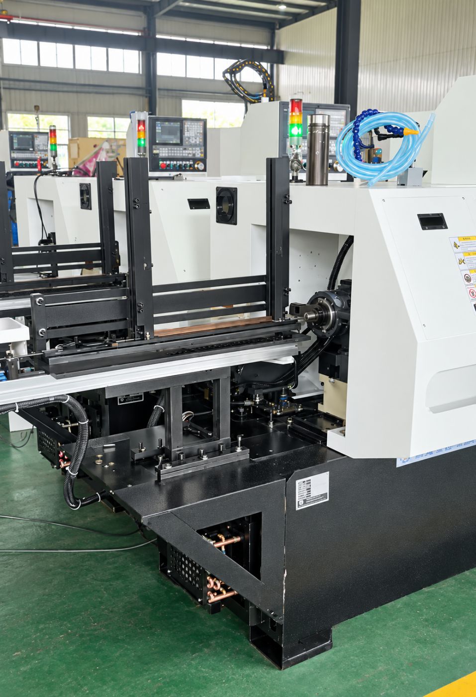
What makes these parts difficult is not the end turning itself, but everything around it: getting bars of different lengths to enter the spindle smoothly, holding a directional profile reliably, and protecting the soft copper surface through handling and transfer between operations. SIPENG CNC configured the solution around the bar cross-section, the length range and the two-end requirement — an automatic feeding CNC lathe with profile-matched collets and internal spindle guidance, arranged as two machines each dedicated to one end.
The Original Method and Its Bottlenecks
The customer previously ran two simple bench lathes, with two operators machining one end each. Based on the customer's own production records, the line produced about 500 pieces per 8 hours at roughly 90% yield.
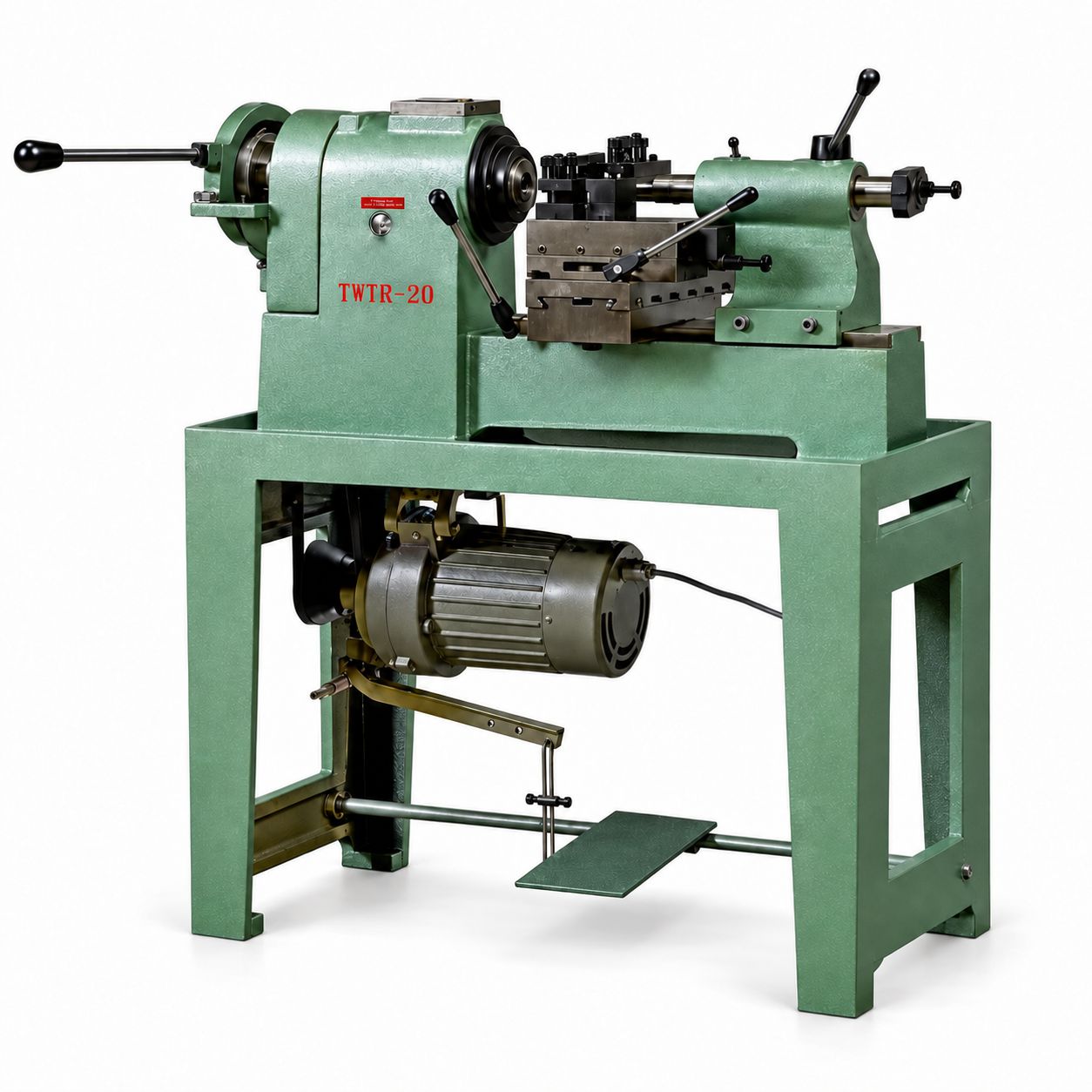
The original method had four main problems:
1. Operator-dependent consistency — feeding, positioning and infeed all relied on the person at the machine, so the operating rhythm and machining state were hard to keep uniform across a shift and across operators.
2. Awkward handling of long bars — at up to 612 mm, manual loading and unloading required the operator to support the bar and control its direction at the same time, adding auxiliary time to every piece.
3. Handling damage between operations — bars passed through loading, first-end machining, reorientation, second-end machining and collection, with repeated pick-and-place and intermediate stacking that risks dents and scrap on soft copper.
4. No stable coolant condition — the original machines could not apply cutting fluid, so tool and workpiece conditions were unstable. The new layout brings coolant into the machine configuration together with CNC-controlled feeds.
The New Layout: Two Machines, One End Each
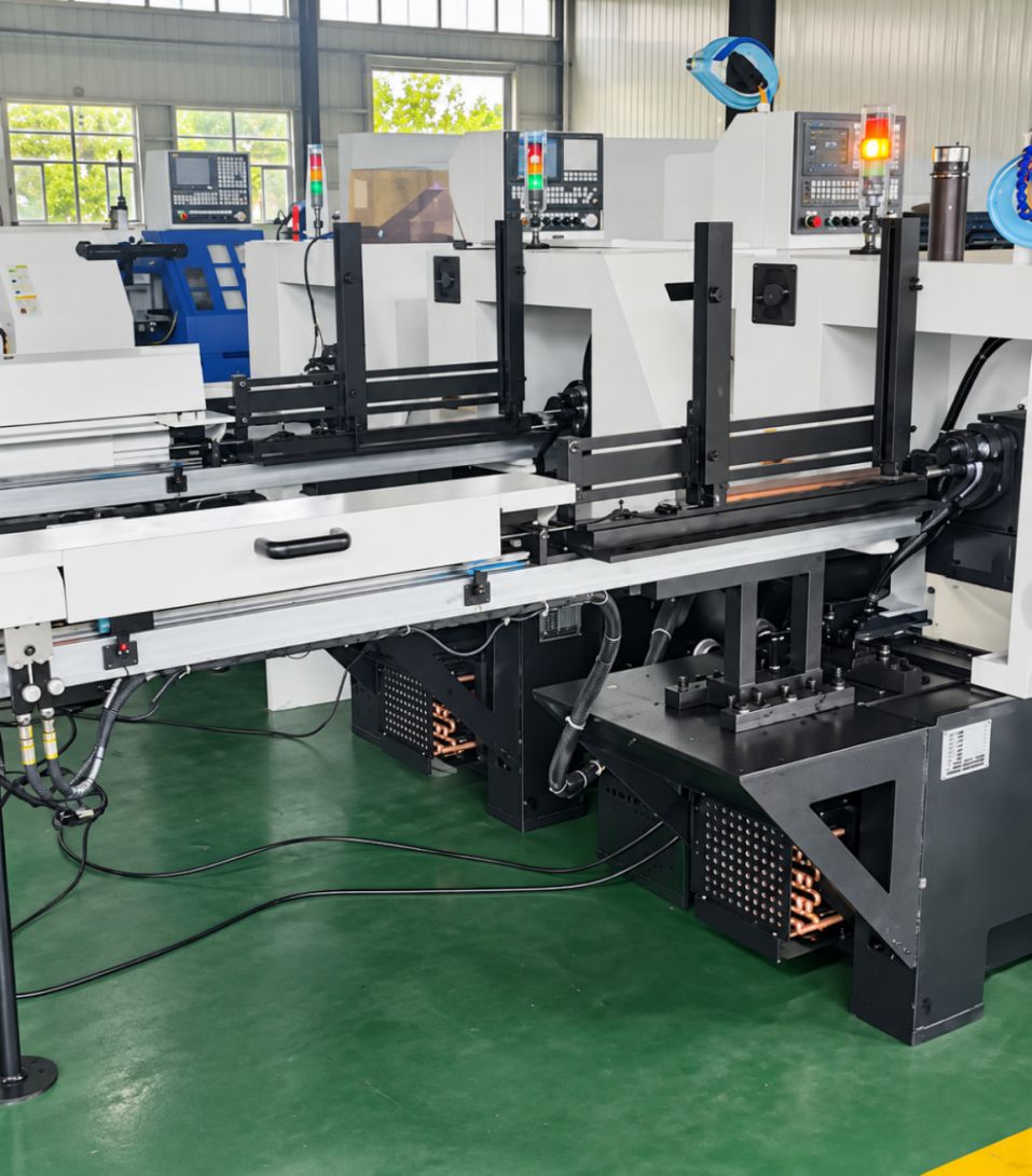
For parts that need turning on both ends, the layout uses two automatic-feeding CNC lathes in sequence: the first machine completes one cylindrical end, then the bar is reoriented and loaded into the second machine for the other end.
Each machine carries a fixed operation, so positioning, tooling and the part program are set once per machine. Every bar is still clamped twice in total — one clamping per machine — and the improvement lies in feeding, machining control and simplified transfer between the two operations. This is deliberately not a "both ends in one setup" solution, and not an unmanned continuous line: the reorientation and transfer between machines remain manual steps by design.
Key Engineering Details
Profile-matched collets — location built from the bar cross-section
The bar has a directional, non-round cross-section, so the workholding must match the profile itself. The dedicated collets are bored to the bar section and close through elastic slitting. Bars are loaded with a consistent orientation — small end down, large end up — so feeding, locating and clamping all repeat in the same relationship.
Spindle guidance — supporting the length range, not just the longest bar
Inside the spindle, a guide tube carries the bar as it enters and passes through. Commissioning showed that the shortest bars (352 mm) place different demands on the guide tube length and its fit with the collet, so the collet and guide configuration were adjusted together. The practical lesson from this project: feeding must be verified at both extremes of the length range, not only with the longest bar — infeed, locating and clamping state all need checking before the solution's applicable range is confirmed.
CNC feeds and coolant — a stable process instead of a practiced hand
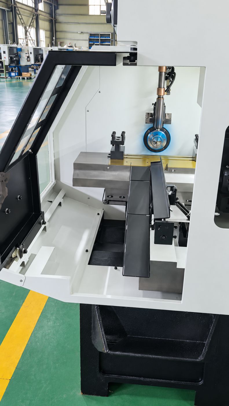
Infeed is controlled by the CNC program and cutting fluid is applied in the enclosure, giving the tool and workpiece a stable thermal and frictional condition. The effect shows up in the customer's output and yield figures below; since the customer has not supplied tolerance, surface-finish or tool-life records for this project, no additional claims are made on those metrics.
Process Flow
Blank picking → bars loaded into the first machine's magazine with the profile direction as specified → automatic feeding and first-end machining → bar reoriented and loaded into the second machine → second-end machining → finished bars collected and stored.
The point of this sequence is to keep bar direction, machining order and collection unambiguous, and to remove unnecessary intermediate stacking and repeated handling. Transfer and reorientation between the two machines remain part of the process and are accounted for in the customer's production figures.
Results
From the customer's own production records on this project:
Original method: about 500 pieces per 8 hours, yield around 90%. New layout: over 1,200 pieces per 8 hours, yield around 99%.
These figures reflect the application result at the customer's site; the counting conditions and product mix are subject to the customer's production records. Because the customer's operator arrangement for the new layout is not yet finalized, no labor-saving ratio is derived from this project.
Project Value
The core of this project is turning a long-profile bar requirement into a matched set of machine, feeding, workholding and process configurations: the profile-matched collet builds location from the bar section, the spindle guide adapts to the length range, automatic feeding removes manual auxiliary operations, and two machines in sequence complete the two ends with fixed, repeatable conditions.
For similar long-profile parts, machine selection should evaluate cross-section, length range, end-machining requirement and inter-operation transfer together — only when these conditions are verified as a set does the output improvement become sustainable.
Send us your part drawing, material grade, bar section, length range and production target, and SIPENG CNC will evaluate the machine, feeding, workholding, tooling and process configuration for your application.